Shark HNG-3530 Скачать руководство пользователя страница 5

97-610, 97-6152  •  REV. 7/04

5


 PRESSURE 

W

ASHER  


OPERA

T

OR’S MANU

AL

INTRODUCTION

Thank you for purchasing our Pressure Washer.

This manual covers the operation and maintenance of
the 301001D, 301007D, 352001A, 352007A, 402001A,
402007A, 402001B, 402007B, 402001C, 402007C,
502001A, 502007A, 502001B, 502007B, 502001C,
502007C, 353001A, 353007A, 353001B, 353007B,
353001C, 353007C, 503001B, 503007B, 503001C and
503007C model washers. All information in this manual
is based on the latest product information available at
the time of printing.

We reserve the right to make changes at any time with-
out incurring any obligation.

This machine was designed for

 maximum use of 4 hours per day,

5 days per week.

Owner/User Responsibility:

The owner and/or user must have an understanding
of the manufacturer’s operating instructions and warn-
ings before using this pressure washer. Warning infor-
mation should be emphasized and understood. If the
operator is not fluent in English, the manufacturer’s
instructions and warnings shall be read to and dis-
cussed with the operator in the operator’s native lan-
guage by the purchaser/owner, making sure that the
operator comprehends its contents.

Owner and/or user must study and maintain for future
reference the manufacturers’ instructions

This manual should be considered a permanent
part of the machine and should remain with it if
machine is resold.

When ordering parts, please specify model and
serial number.

IMPORTANT SAFETY

INFORMATION

WARNING: When using this machine basic precau-
tions should always be followed, including the fol-
lowing:

CAUTION: To reduce the risk of
injury, read operating instruc-
tions carefully before using.

1Read the owner's manual

thoroughly. Failure to follow
instructions could cause mal-
function of the machine and
result in death, serious bodily
injury and/or property dam-
age.

2. All installations must comply with local codes. Con-

tact your electrician, plumber, utility company or
the selling distributor for specific details.

To comply with the National Electrical code (NFPA
70) and provide additional protection from risk of
electric shock, this pressure washer is equipped
with a UL approved ground fault circuit interrupter
(GFCI) power cord for machines rated 250V 30
amp or less, single phase.

3. Know how to stop the machine and bleed pres-

sures quickly. Be thoroughly familiar with the con-
trols.

4. Stay alert.  Watch what you are doing.

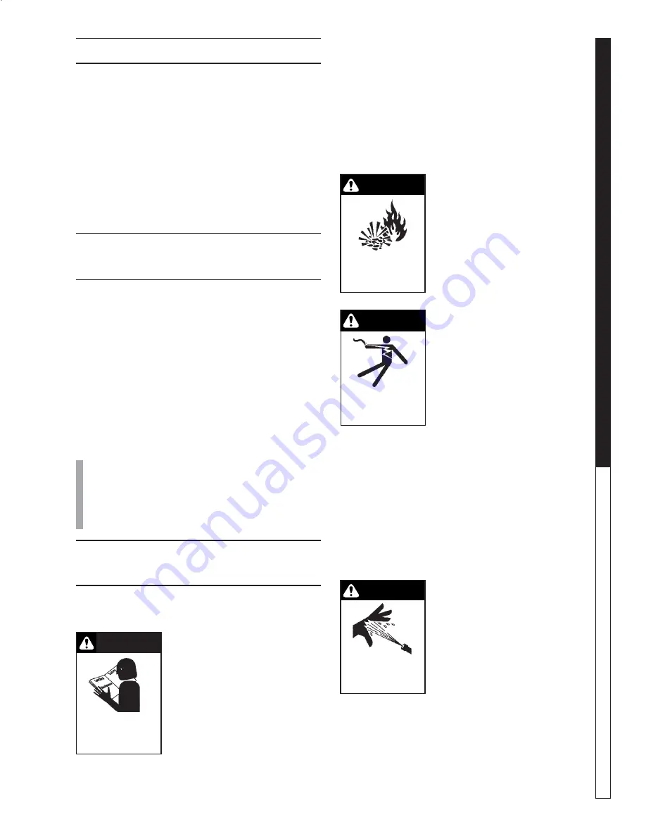
WARNING: Flammable liquids
can create fumes which can ig-
nite causing property damage
or severe  injury.

5. Risk of explosion - Do not

spray flammable liquids or
operate in an explosive loca-
tion. Operate only where
open flame or torch is permit-
ted.

WARNING: Keep water spray
away from electrical wiring or
fatal electric shock may result.
Read warning tag on electrical
cord.

6. To protect the operator from

electrical shock, the machine
must be electrically
grounded.  It is the  responsi-
bility of the owner to connect

this machine to a UL grounded receptacle of proper
voltage and amperage ratings.  Do not spray wa-
ter on or near electrical components.  Do not touch
machine with wet hands or while standing in wa-
ter.  Always disconnect power before servicing.

WARNING: Spray gun kicks back. Hold with both
hands.

7. Grip cleaning wand securely with both hands be-

fore starting the cleaner. Failure to do this could
result in injury from a whipping wand.

WARNING: Equipment can pro-
duce a high pressure stream of
fluid that can pierce skin and its
underlying tissues, leading to
serious injury and possible
amputation.

8. High pressure developed by

these machines can cause
personal injury or equipment

damage. Use caution when operating. Do not di-
rect discharge stream at anyone or at any part of
the body, or severe injury or death will result. This
machine is to be used only by qualified operators.

READ OPERATOR’S

MANUAL

THOROUGHLY

PRIOR TO  USE.

CAUTION

WARNING

RISK OF INJECTION

OR SEVERE INJURY
TO PERSONS. KEEP

CLEAR OF NOZZLE.

WARNING

RISK OF EXPLOSION:

DO NOT SPRAY

FLAMMABLE

LIQUIDS.

WARNING

KEEP WATER SPRAY

AWAY FROM

ELECTRICAL WIRING.

Содержание HNG-3530

Страница 1: ...For technical assistance or the SHARK dealer nearest you call 1 800 771 1881 or visit our website at www shark pw com 97 610 OPERATOR S MANUAL HNG 4020 HNG 3530 HNG 5030 HNG...

Страница 2: ......

Страница 3: ...17 Troubleshooting 18 19 Maintenance Service 20 23 Heating Coils 20 Propane Gas 21 Burner Features 21 22 BurnerTroubleshooting 22 23 Preventative Maintenance Schedule Oil Change Record 24 Hose Spray...

Страница 4: ...model and serial numbers will be found on a decal attached to the pressure washer You should record both serial number and date of purchase and keep in a safe place for future reference 97 610 97 615...

Страница 5: ...utility company or the selling distributor for specific details To comply with the National Electrical code NFPA 70 and provide additional protection from risk of electric shock this pressure washer...

Страница 6: ...pro pane fuel 21 This equipment is designed to run on vapor fuel Do not use liquid fuel Have a quali fied serviceman install and service your equipment 22 Never expose a spark or flame where unburned...

Страница 7: ...Pressure Hose Connect one end to water pump discharge nipple and the other end to spray gun Wand Quick Coupler Pulling the brass collar back allows the insertion of pressure nozzle Note If trigger on...

Страница 8: ...97 610 97 6152 REV 7 04 OPERATOR S MANUAL PRESSURE WASHER 8 INSTALLATION 9 57 I D 49 0 38 3 8 High Pressure Out 11 3 4 27 1 2 44 1 4 Gas In 1 1 2 NPT M 3 0 Fresh Water In 1 0 GHF 1 1 4...

Страница 9: ...to be piped to the burner and a fan installed to bring the air into the area 4 Do not locate near any combustible material Keep all flammable material at least 20 feet away Allow enough space for ser...

Страница 10: ...t f e z i S e p i P n o r I 2 1 4 3 0 1 9 3 3 3 2 8 9 6 0 2 5 9 2 2 9 9 7 4 0 3 3 4 8 1 4 5 8 3 0 4 7 7 5 1 8 9 2 3 0 5 8 9 3 1 3 2 9 2 0 6 7 6 2 1 9 4 6 2 0 7 5 6 1 1 7 3 4 2 0 8 4 8 0 1 7 6 2 2 0 9...

Страница 11: ...tight construction and has a ventilating fan which may be used for exhaust ing air outdoors or has a vented exhaust it is rec ommended that combustion air be supplied to the en closed room through int...

Страница 12: ...b h g i e n a m o r f r e i l p p u s s a g r u o y l l a c y l e t a i d e m m I s n o i t c u r t s n i s r e i l p p u s s a g e h t w o l l o F e n o h p t n e m t r a p e d e r i f e h t l l a c...

Страница 13: ...rward until se cure STEP 2 Pull the spring loaded col lar of the wand coupler back to in sert your choice of pressure nozzle CAUTION Never replace nozzles without engaging the safety latch on the spra...

Страница 14: ...dial and turn to full ON Push pump switch ON or turn to pump position and pull the trigger on the spray gun allowing cold water to flow To activate the gas control valve for hot water push the burner...

Страница 15: ...ly to surface at low pressure for best results limit your work area to sections approximately 6 feet square and always apply detergent from bottom to top Allow detergent to remain on surface 1 3 minut...

Страница 16: ...and insert into one gallon of fresh clean water Pull trigger on spray gun and siphon wa ter for one minute STEP 2 Turn push burner switch to OFF position Open spray gun allowing water to cool Then tu...

Страница 17: ...r e p s b L 3 2 4 7 8 4 r o p a V t F u C r e p U T B 3 6 5 2 9 3 3 d i u q i L l a G r e p U T B 7 4 5 1 9 2 3 0 2 0 1 d i u q i L b L r e p U T B 1 9 5 1 2 1 2 2 1 2 d i u q i L b L r e p t F u C 7...

Страница 18: ...s valve repair replace Faulty flame sensor Test sensor wiring repair replace LOW OPERATING PRESSURE Faulty pressure gauge Install new gauge Insufficient water supply Use larger garden hose Clean filte...

Страница 19: ...l l a t s n I s e n i l t n e g r e t e d n i e l o H e l o h r i a p e R d e g g u l p t e k s a b r e n i a r t S n a e l c d n a e v o m e R e s o o l e v l a v r o t c e l e s n o s n o i t c e n...

Страница 20: ...n open at all times High Limit Hot Water Thermostat For safety each machine is equipped with an adjust able thermostat In the event the temperature of the wa ter should exceed its operating temperatur...

Страница 21: ...ures when extra heat is needed Exterior regulators are needed to control the system Propane bottles are not included with the machine A high pressure regulator should be installed on the pro pane bott...

Страница 22: ...CE TERM TERM TERM TH TP TH TP MILLIVOLT OPERATOR TERMINAL PANEL Check Test To Test Connect Meter Leads To Terminals Switch Flow Burner Contacts Meter Reading Should Be A Complete System 2 3 Closed 100...

Страница 23: ...duced To correct a Clean and tighten switch leads and connec tions b Shorten switch lead wires and or replace with heavier gauge wire c Cycle switch rapidly to clean contacts D Automatic Pilot Dropout...

Страница 24: ...l l a u n n a r o s r u o h 0 0 5 y r e v e n e h t s r u o h 0 5 t s r i f r e t f A r e t l i F r e n r u B n a e l C y l l a u n n A l i o C g n i t a e H m o r F t o o S r e n r u B e v o m e R y...

Страница 25: ...5 5 Green 5030 3010 4020 1 4 12805555 Nozzle SAQCMEG 4005 5 White 5030 3010 4020 1 5 2 3 4 1 ITEM PART NO DESCRIPTION QTY 5 4 12805000 Nozzle SAQCMEG 0005 Red 3520 1 4 12805015 Nozzle SAQCMEG 1505 Yel...

Страница 26: ...Panel Pg 34 For Detail See Float Tank Pg 31 Steam Valve Option For Detail See Burner Assembly Illus To Detergent Valve 73 69 68 65 66 74 79 70 76 75 57 51 53 72 77 71 62 61 26 80 81 78 55 56 6 82 63 8...

Страница 27: ...6 41 44 43 98 46 47 28 35 38 36 9 20 23 24 34 22 25 30 29 28 26 32 33 37 42 27 90 91 6 2 1 14 17 18 19 21 8 50 3 4 6 96 10 11 15 6 45 12 13 58 52 26 62 60 93 94 95 97 91 28 27 5 GPM Machines Steam Val...

Страница 28: ...Reducer 1 2 x 1 4 1 28 2 1089 Hose Barb 1 4 Barb x 1 4 Pipe 90 1 w Steam Option 2 29 2 9000 Clamp Screw 4 3 ITEM PART NO DESCRIPTION QTY 30 2 1037 Tee 1 4 Branch Male Steam Option 1 32 2 0051 Nipple 1...

Страница 29: ...90 1016 Bolt 3 8 x 1 NC HH 8 80 95 07163126 Cover Control Panel Logo 1 95 07163115 Cover Control Panel Remote 1 81 11 0353 Label Control Panel Logo 1 11 0354 Label Control Panel Remote Logo 1 11 0508...

Страница 30: ...k Plastic Universal Float 1 5 2 0151 Plug Float Tank 1 ITEM PART NO DESCRIPTION QTY 6 2 1062 Elbow 1 2 JIC x 1 2 90 1 2 1024 Elbow 1 2 Street 301007 1 2 10062 Nipple Modified Close 3 16 1 7 2 11041 Co...

Страница 31: ...6152 REV 7 04 31 PRESSURE WASHER OPERATOR S MANUAL BURNER ASSEMBLY 19 28 5 4 3 14 15 23 22 13 9 10 20 10 24 11 9 12 5 4 8 4 5 2 5 6 1 16 17 7 25 26 30 18 31 29 21 32 Elec Ignition Only 21 32 Elec Igni...

Страница 32: ...rew 10 x 1 2 TEK 4 16 95 07163097Cover Burner Access 20 Coil 1 17 90 19942 Screw 10 32 x 3 4 Hex Wash SL Mach Blk 2 18 10 99032 Label Pilot Light Hole 1 10 99077 Label Pilot Light Warning 1 ITEM PART...

Страница 33: ...WASHER OPERATOR S MANUAL CONTROL PANEL EXPLODED VIEW Steam Valve Option Steam Valve Option Detergent Remote Operating System For Internal Detail See Electrical Box Pages 36 38 40 9 13 12 15 10 10 7 8...

Страница 34: ...4 6 Nozzle See Page 21 1 7 2 30152 Valve Metering 1 4 Hose 1 8 4 02080000 Tube 1 4 x 1 2 Clear Vinyl 10 ft 9 2 1905 Strainer 1 4 w Check Valve 1 10 2 9040 Clamp Hose UNI 46 54 3 11 2 30151 Valve Flow...

Страница 35: ...Pages 7 6 0504 Block Terminal 4 Pole 1 8 Contactor See Specifications Pages 9 Overload See Specifications Pages 10 6 1401590 Valve Deter Less Solenoid Remote 1 6 140160 Solenoid Coil 120V Remote 1 11...

Страница 36: ...97 610 97 6152 REV 7 04 OPERATOR S MANUAL PRESSURE WASHER 36 TIME DELAY ELECTRICAL BOX EXPLODED VIEW GROUND 11 17 18 1 5 4 6 12 10 20 3 7 9 2 8 14 16 15 13 Detergent Valve Remote 19 3 5 Remote Only...

Страница 37: ...See Specifications Pages 9 Overload See Specifications Pages 10 6 1401590 Valve Deter Less Solenoid Remote 1 6 140160 Solenoid Coil 120V Remote 1 11 2 1089 Hose Barb 1 4 Barb x 1 4 Pipe 90 Remote 2 I...

Страница 38: ...7 610 97 6152 REV 7 04 OPERATOR S MANUAL PRESSURE WASHER 38 AUTO START ELECTRICAL BOX EXPLODED VIEW 11 17 18 1 5 4 6 12 10 14 16 15 13 Detergent Valve Remote 3 7 9 2 8 19 21 20 19 22 3 23 5 Remote Onl...

Страница 39: ...RT NO DESCRIPTION QTY 10 6 1401590 Valve Deter Less Solenoid Remote 1 6 140160 Solenoid Coil 120V Remote 1 11 2 1089 Hose Barb 1 4 Barb x 1 4 Pipe 90 Remote 2 12 2 9000 Clamp Hose UNI 46 54 Remote 2 1...

Страница 40: ...4 5 1018 10 230V 3ph 60Hz 2BK57H 5 405057001Hx1 3 8 503007C GM5030 5 1915 5 40506701 2BK67H 24MM 5 512024 5 1018 10 460V 3ph 60Hz 2BK57H 5 405057001Hx1 3 8 Pump Pulley Pump Bushing Motor Voltage Motor...

Страница 41: ...138 BX36 2 5 604036 6 4013 6 5013 6 60111 1 AMP 6 02294 8 10 6 0229810 503007C 5 511138 BX36 2 5 604036 6 4007 6 5011 6 60111 1 2 AMP 6 02295 8 10 6 0229810 Bushing Belts Belt Motor Motor Trans Primar...

Страница 42: ......

Страница 43: ...buildup rust corrosion or thermal expansion 4 Damage to components from fluctuations in electrical or water supply 5 Normal maintenance service including adjustments fuel system cleaning and clearing...

Страница 44: ...Form 97 610 Revised 7 04 Printed in U S A...

Отзывы: