background image

26

Product Version 1.0 | Revision E | Released 2022-12-09

ABOUT DMX

The fixture can be controlled using signals sent by a DMX controller on a number of DMX channels. 
DMX is the USITT DMX512-A standard, based on the RS-485 standard. The signal is sent as DMX data from a console 
(or a controller) to the fixtures via a shielded twisted pair cable designed for RS-485 devices. 
The cables can be daisy chained between the fixtures, and up to 32 fixtures can be connected on the same DMX link. 
Up to 300 m. (~1000ft.) of cable is achievable with high quality DMX cables. All DMX links must be terminated by con-
necting a DMX termination plug to the last fixture´s 5 pin DMX out connector.

PLEASE NOTE! STANDARD MICROPHONE CABLE IS NOT SUITABLE FOR TRANSMITTING DMX.UP TO 32 FIXTURES 
CAN BE LINKED TO THE SAME DMX CHAIN. ADDITIONAL FIXTURES WILL OVERLOAD THE LINK.

DMX START ADDRESS

The fixture can be operated in different DMX modes. For any of the modes, the first channel used to receive data from 
a DMX control device is known as the DMX start address.
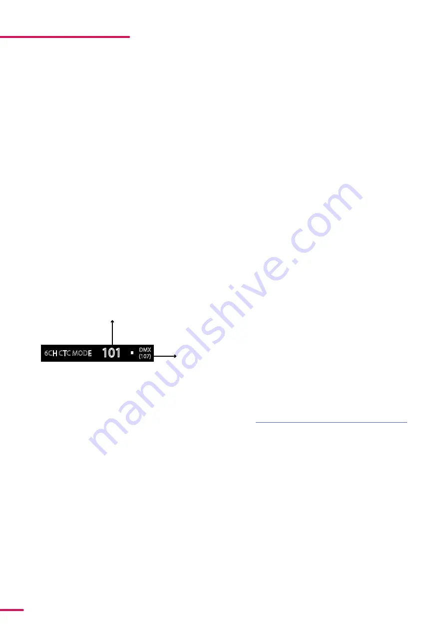
For independent control, each fixture must be assigned its own DMX start address. For example, if the first RGBW 
fixture is set to 6ch CTC DMX mode with a start DMX address of 101, the following RGBW fixture in the DMX chain 
should then be set to a DMX address of 107. As the first fixture uses all the first 6 DMX channels, including channel 101, 
the next available channel is 107 (101+6=107 >> 107).
If two or more fixtures have the same DMX start address, they will behave identically. Incorrect settings will result in 
unpredictable responses from the lighting controller. Address sharing can be useful for diagnostic purposes and sym-
metrical control.

SET/EDIT DMX ADDRESS

The DMX address is shown on the OLED display in the 
control panel. To change the address setting, press the 
up and down arrows. When the desired address is dis-
played, press ENTER to save the setting. For your con-
venience, the next available DMX address is displayed 
to the right. Note that channel spacing is determined 
by the number of channels of the DMX mode.
See "User Interface" on page 24 for instructions on us-
ing the display panel. 
The  fixture also offers the option to set the DMX ad-
dress through RDM. 

PLEASE NOTE! POI VERSIONS ARE ADDRESSABLE VIA RDM. SEE “

POI PERMANENT OUTDOOR INSTALLATION

”.

CONFIGURING THE DEVICE FOR DMX CONTROL

6CH CTC MODE

101

(107)

DMX

DMX address

Next 

available

DMX address

Figure 21: Display

SETTING THE DMX MODE

From firmware version 3 onwards, a legacy and standard set of DMX modes are available. To select the DMX mode of 
choice, a menu layer is implemented. To access the modes:

1.  Press [ENTER]
2. “MODE” is displayed, Press [ENTER]
3. “Select Mode” and current DMX mode is displayed. 
4. Press [Up] or [Down] to enter DMX Operation 

Mode.

5. Press [ENTER]
6. Press [Up] or [Down] to select “Standard” or “Lega-

cy” DMX modes. 

7. Press [ENTER]
8. Press [ESC]
9. Press [Up] or [Down] to navigate to list of DMX 

modes.

10. Press [ENTER]
11. Navigate to DMX mode of choice by pressing [UP] 

or [DOWN]

12. Press [ENTER]

DMX CHARTS

The fixture operates in different DMX modes. Each DMX mode has its own DMX chart.  All DMX charts are available for 
download at www.sgmlight.com under the respective product, or upon request via [email protected]

Содержание P-6

Страница 1: ...USERMANUAL P 6 Product Version 1 0 Document Revision E Released 2022 12 09...

Страница 2: ...ect to change without notice SGM and all affiliated companies disclaim liability for any injury damage direct or indirect loss consequential or economic loss or any other loss occasioned by the use of...

Страница 3: ...3 Product Version 1 0 Revision E Released 2022 12 09 POI VERSION All dimensions in millimetres and inches Drawing not to scale DIMENSIONS...

Страница 4: ...3 INSTALLATION POI FIXTURE 13 Identification and terminology 14 Unpacking 14 Application considerations 14 Connecting temporary Power 15 Connecting temporary signal 16 Settings and Fixture Defaults 17...

Страница 5: ...NDALONE OPERATION 28 FIXTURE PROPERTIES 28 Factory default 28 LED Engine 28 Individual fixture settings 29 CONTROL MENU 31 RDM 31 Supported RDM functions 31 Sensors 32 ACCESSORIES 32 Filter frames 32...

Страница 6: ...from objects to be illuminated Install only in accordance with applicable building codes Ensure a minimum clearance of 0 3 m 12 in around the cooling fans Do not paint cover or modify the device and d...

Страница 7: ...with power and data cable leads are not intended for installation in permanently installed conduit or containment When installing luminaires in a permanent in stallation ensure cable leads are instal...

Страница 8: ...t to change without notice IDENTIFICATION AND TERMINOLOGY B A A 24 x RGBW LEDs B Tilt lock C Cooling fans D Control panel E OLED Display F Rubber feet G GORE TEX membrane H DMX in and out I Power in a...

Страница 9: ...e It has adequate ventilation It is not immersed or submerged in water TRANSPORT HANDLING Always use the supplied packaging or suitable flight case for transportation and storage Never carry the fixtu...

Страница 10: ...8 8 and a lock nut For longer term installations choose outdoor rated hardware 3 Align the omega bracket with the fixture base For standard Omega Bracket insert the fasteners into the fix ture base br...

Страница 11: ...t wing screws one on each side by turning them counter clockwise Tilt the fixture to the angle desired and hold it Lock the position by re tightening both tilt lock screws clock wise CAUTION ALWAYS LE...

Страница 12: ...ed XLR connectors suitable for outdoor use Terminate the DMX out cable of the last fixture in the data link with a 120 ohm DMX termination Note that SGM fixtures provide a passive DMX Thru signal as D...

Страница 13: ...vary from received products This is subject to change without notice A A 24 x RGBW LEDs B POI Tilt lock C Cooling fans D LED indicator E GORE TEX membrane F DMX in and out G Power in and out H Handle...

Страница 14: ...igned for use in outdoor installations This means that it is protected from Dust to the degree that dust cannot enter the device in sufficient quantities as to interfere with its operation High pressu...

Страница 15: ...roducts rdm addressing tool STEP 2 Connect the bare end data cable to the POI Up loader cable for POI fixtures STEP 3 Connect the USB up loader cable for POI fixtures to a computer with a USB Type A p...

Страница 16: ...fixture Look for the LED indicator to blink to confirm setting change DMX modes for POI and Std versions are identical Refer to CONFIGURING THE DEVICE later in this manual for specifics for more info...

Страница 17: ...ake sure the fixture is powered on be fore taking the following steps STEP 1 Using a SGM magnetic spanner tool place the magnet close to the LED indicator and wait for 3 seconds The LED indicator will...

Страница 18: ...ture The POI wash fixture may be installed in any orientation and it might take up to two brackets per fixture Depending on the structure please use appropriate and secure methods for mounting the Ome...

Страница 19: ...Countersunk Bolts Flat Bracket 8mm or smaller screw or bolt to structure 8mm or smaller screw or bolt to structure Fixture 13mm 0 5in hole diameter for attachment point M10 Stainless Steel Bolts POI O...

Страница 20: ...HE SLOT WITH 6 8 SERIES LABEL IS FACING AWAY FROM THE CENTER OF THE FIXTURE BOLTS TO MOUNTING SURFACE WILL USE THIS SLOT M10 Countersunk Bolts POI Universal Bracket Fixture Using a bolt through this s...

Страница 21: ...en to the surface Using the holes shown use appropriately rated fasteners for both location and surface material and construction Fasten ers should be no larger than M6 Use the supplied countersunk M1...

Страница 22: ...ig nose keys The fixture can be tilted in any orientation To adjust the tilt angle in POI fixtures Loosen the two tilt lock kobs one on each side by turning them counter clockwise using the small pig...

Страница 23: ...ut the SGM POI DMX cable For permanent installations have a qualified electrician wire the mains cable directly to a suitable branch circuit For a temporary installation the mains cable may be fitted...

Страница 24: ...ning on the fixture make sure the power cable is properly connected When the fixture is powered on it will boot and reset before displaying the selected operating mode and DMX start address Navigate t...

Страница 25: ...Operational mode B DMX address C External data indicator DMX D External data protocol next available DMX address Figure 20 Display EXTERNAL DATA PROTOCOL D Shows the external data protocol CRMX or DM...

Страница 26: ...ically Incorrect settings will result in unpredictable responses from the lighting controller Address sharing can be useful for diagnostic purposes and sym metrical control SET EDIT DMX ADDRESS The DM...

Страница 27: ...one pro grams can be defined and run from the menus and one of the pro grams can be set to run by default whenever the fixture is powered on Each of the three available standalone programs contains 24...

Страница 28: ...e fixture is installed hanging upside down it might be useful to flip the display so that it is easier to read To flip the display press ENTER and select SETTINGS FLIP DISPLAY or press the up and down...

Страница 29: ...cene 1 24 Red Red value in currently selected scene 0 255 Green Green value in currently selected scene 0 255 Blue Blue value in currently selected scene 0 255 Fade Time Min Fade in transition time to...

Страница 30: ...ay hardware revision Serial Number Display serial number RDM ID Display RDM ID Unique RDM ID for identification DMX View Display received DMX levels Sensors MAIN TEMP Displays fixture temperatures LED...

Страница 31: ...Sensor Definition 0x0201 GET SET Sensor Value 0x0080 GET Device Model Description 0x0400 GET SET Device Hours 0x0401 GET SET Lamp Hours 0x0051 GET Parameter Description 0x0501 GET SET Display Level 0x...

Страница 32: ...for P 6 Figure 25 8 way barndoor for P 6 The P 6 features various optional magnetic holographic filter frames Medium angle 19 Wide angle 45 Elliptical wide angle horizontal 63 x12 Elliptical wide ang...

Страница 33: ...date the fixture with the latest SGM firmware See below how to update the fixture with the latest firmware The SGM Uploader cable is also used for controlling the DMX val ues channel by channel throug...

Страница 34: ...click Upload Firmware The fixture will now update and reboot The Firmware Tool software offers a simple DMX controller featur ing 512 DMX channels for test purposes Figure 29 1 SGM Firmware tool Figu...

Страница 35: ...reless transmitter and connec tions DMX cables were disconnected Inspect DMX cables Fixture operates irregularly abnormally DMX cable polarization is inverted pin 2 3 Install a phase inverter or repla...

Страница 36: ...83060602 83061206 Omega bracket POI with M10 Screws BL WH P N 83060623 83060624 SGM USB uploader cable P N 83062011 SGM USB uploader cable POI P N 83062067 Filter frame Elliptical horz wide angle BL...

Страница 37: ...ht com Conforms to 2014 35 EU Low Voltage Directive Conforms to 2014 30 EU EMC Directive Conforms to 2011 65 EU RoHS2 Directive Conforms to ANSI UL Std 1573 Certified to CSA Std C22 2 No 166 Conforms...

Страница 38: ...38 Product Version 1 0 Revision E Released 2022 12 09 USER NOTES...

Страница 39: ...39 Product Version 1 0 Revision E Released 2022 12 09 SGM LIGHT A S Sommervej 23 8210 Aarhus V Denmark Tel 45 70 20 74 00 info sgmlight com www sgmlight com...

Отзывы: