5
Single-point synchronization
Connection of a TES31A decentralized supply unit
Product Manual – MOVITRANS
®
TES31A Decentralized Supply Unit Synchronization
31
5.3.2
Digital inputs/outputs signal diagram
Block diagram
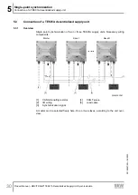
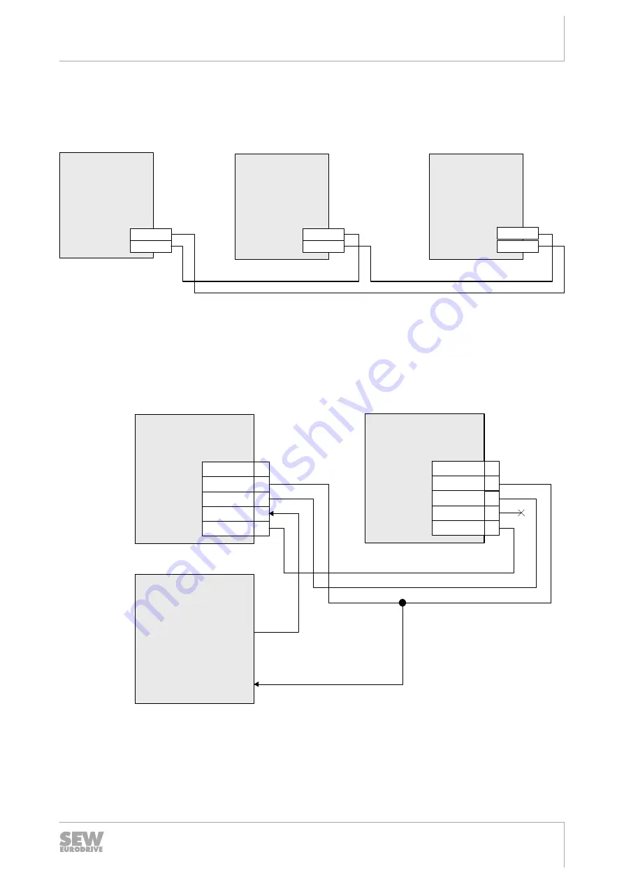
In each case, the digital output is connected 1 to 1 to the digital input of the next syn-
chronization station. The digital output of the final slave is returned to the input of the
master (daisy chain).
...
X5102_1
X5102_2
TES31-Slave 1
TES31-Master
X5102_1
X5102_2
X5102_1
X5102_2
TES31-Slave N
X5102_1
30902664075
Signal diagram of digital inputs/outputs with external terminal enable and status request
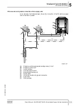
If the enable is implemented via an external terminal signal, an external terminal signal
may be connected at input DI00 of the master instead of output DO00 of the final
slave N. Output DO01 of slave N must be returned without fail to input DI01. In addi-
tion, the signal of an external controller can be supplied to provide information about
the system readiness.
TES31-Slave N
+24V
1
DO01
2
0V24
3
DO00
4
FE
5
X5102_2:
TES31-Master
+24V
1
DI01
2
0V24
3
DI00
4
FE
5
X5102_1:
[1]
...
[2]
[2]
[3]
[1]
30902667659
[1]
External controller
[2]
External terminal signal "Output stage enable"
[3]
External terminal signal "Synchronization: Ready signal"
29190657/EN – 04/2020
Содержание MOVITRANS TES31A
Страница 2: ...SEW EURODRIVE Driving the world...
Страница 69: ......
Страница 70: ......
Страница 71: ......

