


Configuration
Doc. # 177/52701
Rev. 3.3
6-25
outer switches are optional. The steer switches (212B
h
to 212E
h
) must be mapped to digital
inputs.
Steering angle from 3
rd
party CAN device. This can be received via RPDO on object 2624
h
in 0.01º/bit resolution.
To configure steering inputs go to index 2913
h
in the Object Dictionary:
Setup the voltages corresponding to fully left, fully right and straight ahead. Using this
information, Gen4 calculates the steering angle based on the voltage from a steering
potentiometer.
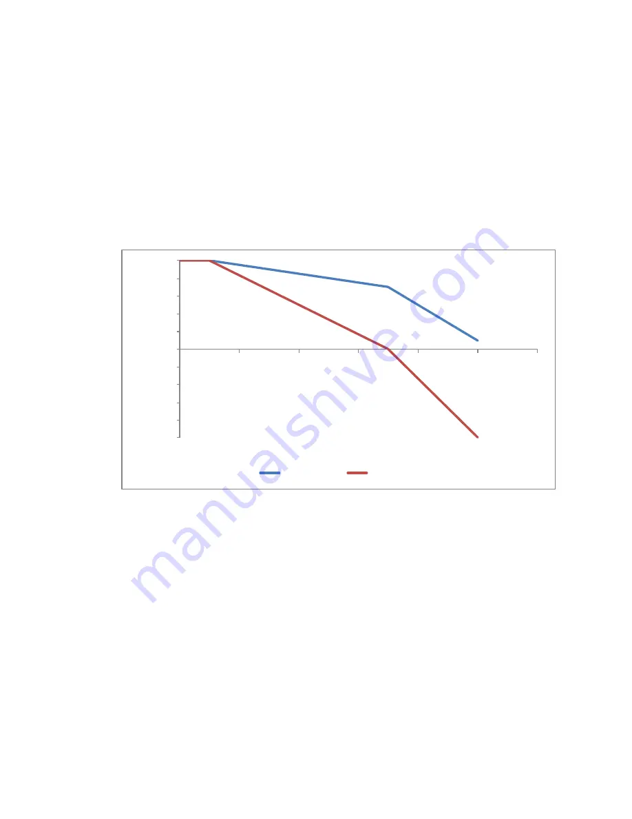
Setup the steering map. This map defines the relationship between the inner and outer
wheel speeds and the steering angle. Each map has 4 user definable points as shown in
Figure 28.
Figure 28 Graph of speed vs. steering angle
The speed and steering angle are normalized. Speed is normalized to maximum vehicle speed
and the steering angle to 90º.
In speed mode, outer wheel speed target and maximum torque is scaled according the outer
wheel map. Inner wheel speed target and maximum torque is scaled to the outer wheel
demands according to the inner wheel map.
In torque mode, both inner and outer wheel maximum speeds are scaled according the outer
wheel map. The outer wheel target torque comes from the throttle. The inner wheel target torque
is scaled to the outer wheel actual torque according the inner wheel map.
In object 2913
h
, 0 to 1 is represented by values in the range 0 to 32767. The inner wheel is
scaled according to the outer wheel. Where a demand (pu) of -1 is shown at 90º for the inner
wheel, this means the inner wheel demand will be equal and opposite to the outer wheel.
The calculated steering angle can be read at 2623
h
. An angle value of -32767 indicates full
steering to the left, +32767 full steering to the right and 0 is straight ahead.
-1
-0.8
-0.6
-0.4
-0.2
0
0.2
0.4
0.6
0.8
1
0
0.2
0.4
0.6
0.8
1
1.2
D
e
m
and
(pu)
Steer angle (pu)
Outer Wheel
Inner Wheel
Содержание Gen4
Страница 1: ...Gen4 Applications Reference Manual Document no 177 52701 Rev 3 3 ...
Страница 9: ...Chapter 1 Introduction ...
Страница 13: ...Chapter 2 About the Gen4 ...
Страница 25: ...Chapter 3 Installation ...
Страница 45: ...Chapter 4 Specification ...
Страница 47: ...Specification Doc 177 52701 Rev 3 3 4 3 CAUTION Repetitive short circuits may damage the controller ...
Страница 50: ...4 6 Isolation Any terminal to the case Meets EN1175 1 1998 and ISO3691 Complies with IEC 60664 ...
Страница 53: ...Specification Doc 177 52701 Rev 3 3 4 9 Dimensions Size 2 models Size 4 models ...
Страница 54: ...4 10 Size 6 models ...
Страница 55: ...Chapter 5 System design ...
Страница 60: ...5 6 Single traction wiring diagram Figure 13 Single traction wiring diagram ...
Страница 61: ...System design Doc 177 52701 Rev 3 3 5 7 Single pump wiring diagram Figure 14 Stand alone pump wiring diagram ...
Страница 63: ...System design Doc 177 52701 Rev 3 3 5 9 On board fuse See On board fuse mounting on page 3 11 ...
Страница 64: ...5 10 Figure 15 Dual traction wiring diagram ...
Страница 70: ......
Страница 71: ...Chapter 6 Configuration ...
Страница 110: ......
Страница 111: ...Chapter 7 Monitoring Gen4 ...
Страница 122: ......
Страница 123: ...Monitoring Doc 177 52701 Rev 3 3 A 1 ...