background image

16

Installation and Service Manual

Note:

Cleaning and sanitizing is not required for potable water circuits. Potable water lines should remain con-
nected and operational during the cleaning and sanitizing procedures for syrup circuits.

CLEANING THE DISPENSING VALVES

1.

Disconnect each syrup container from its product line,
tank connector, or bag-in-box connector. Remove
product from the lines by purging with clean warm
tap water until syrup has been fully purged from the
product lines and valves.

2.

Clean all lines and fittings with cleaning solution and
rinse with clean, room temperature water to remove
all traces of residual product.

3.

For the A&W pre-mix valve, clean dispense nozzle in
place with sanitizing solution and nozzle brush, up to
internal shut off port.

CLEANING THE PRODUCT LINES

1.

To clean each valve product line, attach the valve
product lines to the pressure tank containing the
cleaning solution or place the bag-in-box connector
in cleaning solution. Remove branch port cover on
bag-in-box connector to allow suction of cleaning
solution. Make sure each line is completely filled.
Pressurize the lines by pulsing the valves.

PRESSURIZING THE PRODUCT LINES

1. For 15 seconds turn dispensing valve 

“on”

“off”

,

and then immediately 

“on”

 again for 15 cycles.

2. Allow the valve to remain flowing for 3 minutes.

3. Repeat pulsing and flowing the valves again until all

cleaning solution has been used.

4. Flush the cleaning solution from the lines with clean

water after a minimum of 3 minutes, by pulsing the
valves as described above.

5. Attach each valve product line to the pressure tank

containing the sanitizing solution or place the bag-in-
box connector in sanitizing solution. Remove branch
port cover on  bag-in-box connector to allow suction
of sanitizing solution. Be sure all connections are
cleaned and sanitized before connecting to each prod-
uct line.

6. Pressurize and fill the lines with sanitizing solution.

Make sure lines are completely filled. Allow the sani-
tizing solution to flow through each valve while acti-
vating the valves for 15 cycles (as described in “Pres-
surizing the product lines”).

a.

Leave valves 

“off”

 and allow to stand pressur-

ized for 30 minutes.

b.

Activate the valves for two (2) cycles (as de-
scribed in “Pressurizing the product lines”). Flush
remaining sanitizer continuously through the
valves.

7. Reconnect the syrup containers to their respective

circuits. Prepare the unit for operation.

8. Draw drinks to refill lines and flush the sanitizing

solution from the dispenser. Taste the beverage to
verify that there is no off-taste (chlorine).

BEVERAGE SYSTEM CLEANING

USER MAINTENANCE

CLEANING AND SANITIZING PROCEDURE

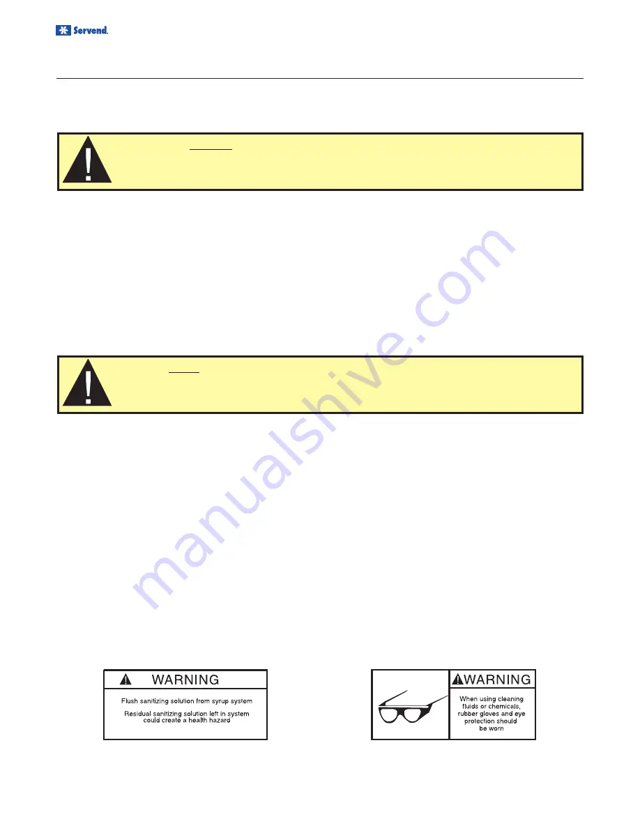
Caution:


It is required

 that the Carbonated Water Lines should remain connected and opera-

tional during cleaning and sanitizing of the syrup circuits. Sanitizing of the valve without the
Carbonated Water side operation may leave bacteria in the nozzle, diffuser, and syrup tube.

Caution:

 Do not allow cleaning and sanitizing solutions to remain in syrup systems longer than

recommended contact time. Exceeding contact time will result in damage to valve components.

Sanitize the beverage system at initial start-up as well as regularly scheduled cleaning. The drain pan must be in
place under soda valves, to carry away detergent and sanitizing agents that will be flushed through valves.

Содержание BLADE TOWER

Страница 1: ...icy of continuous product development and improvement this information is subject to change at any time without notice April 01 2008 REV0 Notice DO NOT throw this manual away This manual contains impo...

Страница 2: ...__________________________________________________ Serial Number _______________________________________________________________________ Installation Date _____________________________________________...

Страница 3: ...NIT INSPECTION 6 PRE INSTALLATION CHECK LIST 6 STARTING YOUR BEVERAGE SYSTEM AND DISPENSER 6 SPECIFICATIONS 6 BLADE TOWER DIMENSIONS 7 COUNTER TOP FOOTPRINT 7 UNIT INSTALLATION 8 BASIC B I B SYSTEM PR...

Страница 4: ...OW TO DISASSEMBLE TOWER COMPONENTS 14 CLEANING EQUIPMENT AND SUPPLIES 14 CLEANING SANITIZING THE DISPENSING VALVES PRODUCT LINES 14 MAINTENANCE SCHEDULE 15 NIGHTLY SHUTDOWN PROCEDURE 15 CLEANING AND S...

Страница 5: ...CO2 gas causes tremors which are followed rapidly by loss of consciousness and suffocation If a CO2 gas leak is suspected particularly in a small area immediately ventilate the area before repairing...

Страница 6: ...tank Gas connectors for tank Beverage dispenser Beverage tubing CO2 tank Beverage tanks Stepless Oetiker clamps Chain for CO2 tank Double Check Doyouhaveenoughspacetoinstallthedispenser Is the counter...

Страница 7: ...ER TOP AREA CAUTION Cutting the counter top may decrease its strength Counter should be braced to support the dispenser counter top weight plus ice storage ca pacity and weight of icemaker if applicab...

Страница 8: ...carbonator tank Do so by lifting the pressure relief valve tab on the carbonator tank until water comes out of the relief valve 7 Check water and beverage lines for leaks if there are no leaks fasten...

Страница 9: ...ration below shows the optional flush mount drain setup Part Number 020001388 If using the optional flush mount drain be sure to plumb according to local codes PLUMBING DIAGRAM LOCATION A plumbing dia...

Страница 10: ...10 Installation and Service Manual INSTALLATION SINGLE TOWER PLUMBING DUAL TOWER PLUMBING...

Страница 11: ...for 5 seconds 4 Record volume in a volume cup or ratio cup 5 Adjust the water flow rate as needed until 10 ounces of water is measured in a 5 second 2 oz sec dis pense Set the syrup flow rate 1 Adjus...

Страница 12: ...nternal External Carbonator tank Combines CO2 gas and tap water to form carbonated water The car bonator is the carbonator tank water pump and wa ter pump motor 5 CO2 cylinder Holds highly pressurized...

Страница 13: ...t Contact MBE at 1 800 367 4233 for more information about our ProActive Maintenance Program 1 Conduct the daily and nightly recommended mainte nance of the machine 2 Perform the monthly recommended m...

Страница 14: ...embly 1 Remove tower housing cover by removing the thumb screw on the side 2 Turn OFF both shut off valves on the flow control base and remove pressure by pulling the dispense handle to the ON positio...

Страница 15: ...ild detergent Rinse with potable water Weekly Outside dispenser cabinet Wash with clean water and mild detergent Wipe dry Every 3 months Syrup circuits Sanitize each syrup circuit See Cleaning and San...

Страница 16: ...uct line to the pressure tank containing the sanitizing solution or place the bag in box connector in sanitizing solution Remove branch port cover on bag in box connector to allow suction of sanitizin...

Страница 17: ...tap water 4 Connect syrup connector to BIB connector and im merse both into Bucket 1 A bag side connector can be created by cutting the connector from an empty disposable syrup bag 5 Draw rinse water...

Страница 18: ...or to the proper setting Defective HP regulator Check repair replace HP regulator CO2 line pinched kinked or obstructed Check repair replaceCO2 line One valve will not dispense anything Is there power...

Страница 19: ...s Clogged No Power Check Liquid Level Control Board For Clogging For Mechanical For Clogging For Mechanical Syrup Push Pressure Check Valves in Water and Product Lines If soda water check valve is bad...

Страница 20: ...N 47172 1868 Tel 812 246 7000 800 367 4233 Fax 812 246 9922 www manitowocbeverage com In accordance with our policy of continuous product development and improvement this information is subject to cha...

Отзывы: