8
SERIAL CABLES PCI-SWGEN3-81U PCI Switch Board User’s Manual
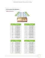
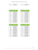
SFF8643 connector
Pin No.
Pin names
Direction
Description
A1
SSD_CLK_0_N
OUT
HCSL type, non-SSC 100MHz
reference clock output
A2
SSD_CLK_0_P
OUT
A4
PEX_GF_PERP3
IN
A5
PEX_GF_PERN3
IN
A7
PEX_GF_PERP2
IN
A8
PEX_GF_PERN2
IN
B1
PORT_GOOD#_0
OUT
1.
Assert “L” state when port link up without any error.
2.
H or H to L translation represents physical error
detected or link in Gen1 or Gen2 speed.
B2
SSD_RESET#_0
OUT
Reset output to device
B4
PEX_GF_PERP1
IN
B5
PEX_GF_PERN1
IN
B7
PEX_GF_PERP0
IN
B8
PEX_GF_PERN0
IN
C1
NC
C2
NC
C4
PEX_CONN_PETP3
OUT
C5
PEX_CONN_PETN3
OUT
C7
PEX_CONN_PETP2
OUT
C8
PEX_CONN_PETN2
OUT
D1
SSD_PRE0
IN
Present “H” and IFDET “L” indicates an enterprise NVMe
SSD detected
D2
SSD_IFDET#0
IN
D4
PEX_CONN_PETP1
OUT
D5
PEX_CONN_PETN1
OUT
D7
PEX_CONN_PETP0
OUT
D8
PEX_CONN_PETN0
OUT
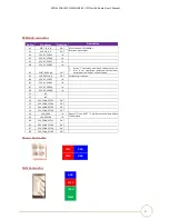
Power Connector
P12V
GND
P12V
GND
FAN Connector
GND
P12V
TACH
PWM


