background image

CHAPTER 4. COMMON RECE

I

VER OPERAT

I

ONS

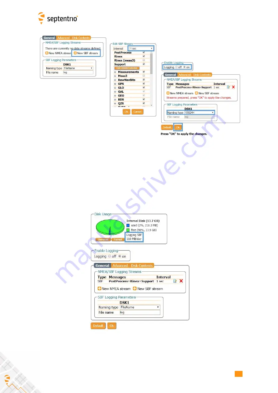
Figure 4-14:

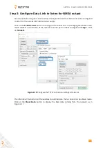
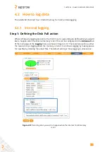
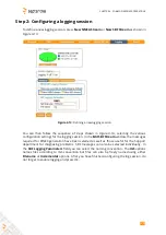
Follow the sequence of windows to fully con

gure the logging session

Step 3: Verifying the configuration

When you have

nished con

guring the logging session, the

Log Sessions

window will show

a summary of the de

ned logging sessions as in Figure 4-15. An estimate of the daily size of

data generated with the current logging con

guration is also given.

Figure 4-15:

A summary of the newly de

ned logging sessions showing the

expected amount of data generated daily

30

Содержание AsteRx SB ProDirect

Страница 1: ...AsteRx SB ProDirect User Manual ...

Страница 2: ...7 2 of the AsteRx SB ProDirect firmware July 13 2020 Copyright 2000 2020 Septentrio NV SA All rights reserved Septentrio Greenhill Campus Interleuvenlaan 15i 3001 Leuven Belgium http www septentrio com Phone 32 16 300 800 Fax 32 16 221 640 Septentrio 2 ...

Страница 3: ...a Ethernet 10 3 1 3 Connecting to the web interface via USB 11 3 1 4 Connecting via COM 12 3 2 HOW TO CONFIGURE THE ASTERX SB PRODIRECT FOR RTK 13 3 2 1 How to configure the AsteRx SB ProDirect in RTK rover mode via Ethernet 13 3 3 HOW TO CONFIGURE THE ASTERX SB PRODIRECT FOR ATTITUDE 15 4 Common Receiver Operations 20 4 1 HOW TO CONFIGURE SBF AND NMEA OUTPUT 20 4 1 1 Output over a serial COM conne...

Страница 4: ...x SB ProDirect receiver is declared as class A suitable for residential or business environment In a domestic environment this product may cause radio interference in which case the user may be required to take adequate measures 1 1 2 ROHS WEEE Notice The AsteRx SB ProDirect is compliant with the latest WEEE RoHS and REACH directives For more information see www septentrio com en environmental com...

Страница 5: ... double isolated construction and must match the specifications of the provided power supply Statement 2 Ultimate disposal of this product should be handled according to all national laws and regulations Statement 3 The equipment and all the accessories included with this product may only be used according to the specifications in the delivered release note manual or other documents delivered with t...

Страница 6: ...hich cover a wide array of technical and less technical topics The Knowledge Base is part of Septentrio s Support Portal which can be accessed through the support section of the Septentrio website see below The Septentrio website has a dedicated Support section http www septentrio com support where the User Manual the Firmware Reference Guide and the latest officially supported Firmware version are ...

Страница 7: ... a wide array of different systems but it can also be used as a single antenna receiver for systems which do not require heading 2 1 Physical and Environmental Specifications Size 102 x 36 x 118 mm 4 0 x 1 4 x 4 6 in Weight 497 g 1 1 lb Input voltage 5 to 36 V DC Power consumption 1 00 W typical single antenna 1 35 W typical dual antenna Operating temperature 30 C to 65 C 22 F to 149 F Storage tempe...

Страница 8: ...anel of the AsteRx SB ProDirect 2 2 2 Rear Panel Figure 2 2 shows the layout of the rear panel connectors of the AsteRx SB ProDirect The rear panel has three connectors a 7 pin female PWR COM2 3 USB socket a 7 pin female COM1 GPIO socket and a 4 pin female ETH socket A full description of the connector PIN layout of the rear panel ports can be found in Appendix A Figure 2 2 The rear panel of the A...

Страница 9: ...the rear panel 7 pin female PWR COM2 3 USB socket You may also power the AsteRx SB ProDirect by connecting an appropriate USB cable to the same 7 pin female PWR COM2 3 USB socket using either the recommended Septentrio USB adapter or the USB socket of a PC as shown in Figure 3 1 Figure 3 1 Connecting the receiver though USB using the rear panel PWR COM2 3 USB socket The AsteRx SB can also be power...

Страница 10: ...is not necessary Figure 3 2 Rear panel Ethernet socket Step 2 Open a web browser and connect to the AsteRx SB ProDirect By default the AsteRx SB ProDirect has the hostname http asterxsb xxxxxxx where xxxxxxx are the 7 digits of the serial number of the receiver board inside the AsteRx SB ProDirect This hostname can be used on a local area network to connect to the AsteRx SB ProDirect if the IP add...

Страница 11: ...nected to a LAN network Then connect the power cable to the receiver and make sure the correct input voltage is applied between 4 5 and 36 V DC Figure 3 4 Rear panel 7 pin PWR COM2 3 USB socket Step 2 Open a web browser and connect to the AsteRx SB ProDirect Once connected via USB the AsteRx SB ProDirect can be reached using the default Ethernet over USB IP address 192 168 3 1 as shown in Figure 3...

Страница 12: ...ect the power cable to the receiver and make sure the correct input voltage is applied between 4 5 and 36 V DC Figure 3 6 Rear panel COM 1 socket Step 2 Open RxControl and connect to the AsteRx SB ProDirect Once connected open RxControl on the computer to which the receiver is connected and follow the sequence of steps described in Figure 3 7 to open a connection to the AsteRx SB ProDirect Note th...

Страница 13: ...in a closed network 3 2 1 How to configure the AsteRx SB ProDirect in RTK rover mode via Ethernet Step 1 Enable RTK positioning mode Ensure that RTK is enabled as a positioning mode This can be done in the GNSS Position tab by checking the RTK box in the Position Mode field as shown in Figure 3 8 Figure 3 8 Ensure that RTK is enabled as a positioning mode Step 2 Configure the Ethernet connection On t...

Страница 14: ...ith the base station Step 3 Verifying the configuration If the Base station and rover receivers have been configured correctly then the Communication Ethernet window should appear similar to the window shown in 3 10 Figure 3 10 Ethernet tab of the rover receiver showing a fixed RTK position and reception of RTCMv3 diff corr on receiver port IPR1 14 ...

Страница 15: ...is section details how to configure the AsteRx SB ProDirect in a two antenna setup Step 1 Connect a second antenna Connect a second antenna to the front panel connector labelled AUX ANT as indicated in Figure 3 11 Figure 3 11 Auxiliary antenna connector on front panel Step 2 Configure attitude settings The attitude settings of the AsteRx SB ProDirect can be configured in the GNSS Attitude window as s...

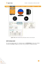
Страница 16: ...igure 3 12 GNSS Attitude window when two antennas are connected GNSS Attitude field The recommended settings for a Heading setup are MultiAntenna mode with attitude calculated using Fixed ambiguities as shown These setting are configured by default 16 ...

Страница 17: ...gitudinal axis in the clockwise direction corresponds to a positive change in the value of the heading offset To better explain this a few examples of possible setups are given below in Figure 3 13 Figure 3 13 Examples of a number of antenna setups and the corresponding heading offsets a The default setup for which the angle between the antenna baseline and the longitudinal axis is 0 and no heading ...

Страница 18: ...ituation where the main antenna is mounted lower than the aux antenna assuming the default antenna setup will result in a positive pitch a shown in Figure 3 14 Figure 3 14 Visual representation of the effect of vertical offset between the two antennas on the Pitch offset Assuming the default antenna configuration the aux antenna being mounted higher will result in a positive value for the pitch 18 ...

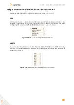
Страница 19: ...OfAtt These blocks are selected automatically when checking the Attitude box when configuring SBF output via the NMEA SBF Out window as Figure 3 15 shows Figure 3 15 SBF blocks containing attitude information NMEA You can output the attitude information from the AsteRx SB ProDirect in NMEA format by selecting the standard NMEA HDT sentence or the Septentrio proprietary HRP sentence as shown in Figu...

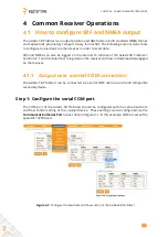
Страница 20: ...4 2 1 and 4 3 detail how to log data on the receiver and how to download data logged on the receiver 4 1 1 Output over a serial COM connection The AsteRx SB ProDirect can be connected via a serial COM cable to an RS 232 compatible secondary device Step 1 Configure the serial COM port The COM port of the AsteRx SB ProDirect should be configured with the same baud rate and flow control setting of the c...

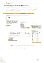
Страница 21: ...In the NMEA SBF Out tab clicking on New NMEA Stream will guide you through the steps needed to configure NMEA output as shown in Figures 4 2 and 4 3 Figure 4 2 Selecting to output NMEA data on COM3 Figure 4 3 Selecting to output the GGA and ZDA NMEA message every second 21 ...

Страница 22: ...t window a second output stream can be configured In the example shown in Figures 4 4 and 4 5 the PVTCartesian SBF data block will be output over COM1 once per second Figure 4 4 Selecting to output SBF data on COM1 Figure 4 5 Selecting to output the PVTCartesian SBF block every second 22 ...

Страница 23: ...e 4 6 Figure 4 6 Summary of all configured data output streams Figure 4 7 shows the actual data output NMEA is in ASCII and is thus readable unlike SBF which is formatted in binary In this example the serial COM was connected to a PC via a USB adapter which maps the serial connection to a virtual COM9 of the PC Figure 4 7 Example showing output of NMEA GGA left panel and SBF PVTCartesian right pane...

Страница 24: ...Figure 4 8 port 600 has been configured as connection IPS1 in TCP2Way mode so data can be received as well as transmitted over the connection When choosing a port number avoid conflicts with other applications such as the commands port 28784 the webserver port 80 the FTP port 21 as well as the default NTRIP port 2101 and the NTP port 123 Note that a new IP port can also be configured by followings th...

Страница 25: ...quence of windows to configure the data you want to output In the example shown in Figure 4 9 the NMEA GGA message will be output every second Ensure that the previously configured IPS1 port is selected for output as highlighted Figure 4 9 Outputting NMEA GGA over the configured IPS1 connection Similar steps can be followed to output SBF messages 25 ...

Страница 26: ... the TCP IP Client button to configure the connection In the highlighted fields insert the IP address or hostname of the receiver and the port number configured in Step 1 Click on Connect Figure 4 10 Configure the TCP IP connection settings in Data Link The info line at the bottom of the window should indicate that a connection has been made Click on the Show Data button to display the GGA data coming...

Страница 27: ...CHAPTER 4 COMMON RECEIVER OPERATIONS Figure 4 11 The Show data window of Data Link showing the NMEA GGA message coming from the AsteRx SB ProDirect 27 ...

Страница 28: ...what you would like to happen when the internal memory is full This can be configured in the Advanced tab of the main page of the Logging menu as shown in Figure 4 12 There are two options either the receiver stops logging when the memory is full or it continues logging by making space for new files by deleting the oldest files The default setting is Stop logging in all sessions Figure 4 12 Selecting...

Страница 29: ...ging session In the Edit SBF Stream window the messages required for RINEX generation have been selected as well as those useful for the Support department for diagnosing problems SBF messages can also be selected individually In the SBF Logging Parameters field you can select the naming convention The IGS options names files according to IGS convention but files can also be freely named using either...

Страница 30: ...n you have finished configuring the logging session the Log Sessions window will show a summary of the defined logging sessions as in Figure 4 15 An estimate of the daily size of data generated with the current logging configuration is also given Figure 4 15 A summary of the newly defined logging sessions showing the expected amount of data generated daily 30 ...

Страница 31: ...irect can be downloaded using the web interface using the Disk Contents tab on the main page of the Logging menu Individual files can be downloaded by clicking on the green download arrow next to the file name as shown in Figure 4 16 Obsolete files can be deleted by clicking the button Figure 4 16 Downloading logged files 31 ...

Страница 32: ...put 1 3A Pink wire with Red heat shrink tube 2 Black GND GND Ground Brown wire with Black heat shrink tube 3 Green RxD3 USB D EITHER Serial COM3 receive line OR Negative USB 2 0 FS device node Selection is done via pin 7 4 Yellow TxD3 Not connected Serial COM3 transmit line 5 Grey RxD2 USB D EITHER Serial COM2 receive line OR Positive USB 2 0 FS device node Selection is done via pin 7 6 White TxD2...

Страница 33: ...to detection 1 µs 15 KΩ pull down 2 Black GND Ground Brown wire with Black heat shrink tube 3 Green COM1 CTS EVENTB COM1 Clear to Send This also connects to the second event EVENTB input It has the same electrical specifications as EVENTA see pin 1 4 Yellow COM1 RTS PPS_OUT COM1 Request To Send or PPS_OUT PPS_OUT low 0V PPS_OUT high 5V PPS_OUT polarity is consistent with command line reference of O...

Страница 34: ... gain at the connectors antenna gain minus cable losses must be in the range 15 to 50dB By default the receiver provides a 3 3V DC supply on both the MAIN and AUX connectors to feed the antennas The supplied antenna voltage can be changed to 5V DC with the command setAntennaVoltage The maximum supported current is 200mA Never inject a DC voltage into the MAIN or AUX connectors as it may damage the...

Страница 35: ...APPENDIX A REAR PANEL PORT DESCRIPTIONS 35 ...

Отзывы: