


Page 42
FiberPatrol Site Planning & Installation Guide
FiberPatrol installation
1. Ensure that there is enough sensor cable in the equipment room to reach the controller in the
equipment rack and to create a 10 m service loop.
2. Run the sensor cable to the designated start point of the detecting cable.
3. If the site plan calls for a splice at the designated start point, ensure that there is enough cable
to reach the splice enclosure on the fence and to create 10 m service loop, and if required, a
13 m isolation loop (optional) then cut the cable.
OR
3. If the site plan calls for a continuous run of cable at the designated start point, leave enough
cable to create a 13 m isolation loop (optional) and continue to deploy the sensor cable around
the perimeter.
4. At each point in the installation where extra cable is required, lay out a sufficient amount of
cable in a figure 8 pattern to cover the feature. If you are pulling the cable around the
perimeter, you must pull back a sufficient amount of cable after the cable is dispensed to cover
the cable length requirement for each feature.
5. Once you have reached the end of the cable reel, leave enough cable to create a 10 m service
loop for the splice (or for fiber termination).
6. If the installation extends past the end of this cable reel, leave enough cable to create a 10 m
service loop for the splice, and continue deploying the sensor cable.
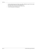
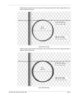
Figure 49 Solid wall conduit


