background image

COMPATIBLE WIRELESS DEVICES

MODEL #

DESCRIPTION

WIRELESS TYPE

POWER TYPE

SWX-201-B 

Small Motion 360° Sensor, PIR

Transmit

Battery

SWX-401-B

Wide View Sensor, PIR

Transmit

Battery

SWX-402-B

Long Range Hallway Sensor, PIR

Transmit

Battery

SWX-851-xx

Wall Switch Load Controller, No Neutral Required, <xx = color>

Transmit & Receive

120-277 VAC

SWX-852-B-xx

Remote Switch (On/Off), <xx = color>

Transmit

Battery

SWX-854-B-xx

Remote Dimming Switch (On/Off, Raise/Lower), <xx = color>

Transmit

Battery

SWX-950

Power Pack Load Controller, 20A

Receive

120/277 VAC

SWX-950-D2

Power Pack Load Controller, 20A, 0-10V Dimming

Receive

120/277 VAC

SWX-950-AX

Hybrid Wireless/Wired Power Pack Load Controller, 20A

Transmit & Receive

120/277 VAC

SWX-950-AX-D2

Hybrid Wireless/Wired Power Pack Load Controller, 20A, 0-10V Dimming

Transmit & Receive

120/277 VAC

The below chart lists the devices that can be used in a 

SENSOR

WORX wireless application. Note that sensors and remote switch & dimmer devices are transmit only devices and 

therefore must be linked to a load controller for switching or dimming of lighting.

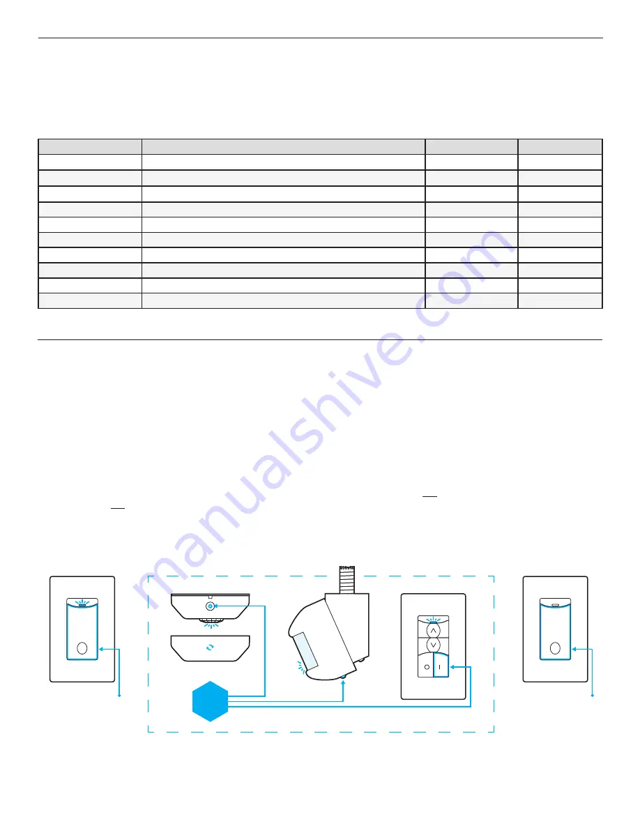
WIRELESS LINKING (PAIRING)

Linking a wall switch controller with a sensor, power pack, dimmer, or another wall switch controller is quickly done via the following procedure:

Step 1.

  Enter pairing mode by holding down the wall switch’s button for 3 seconds until the LED starts alternating blue and white, then release.

Step 2.

  At the sensor (or other remote device), hold down the programming button for 3 seconds until the LED starts alternating blue and white. Releasing will link the sensor with the 

               switch in pairing mode (see note 1 below).

Step 3.

  Repeat step 2 to link another sensor or device.

Step 4.

  When all devices have been linked, exit pairing mode on the wall switch controller by pressing the button 1 time. Pairing will also be automatically closed after 15 minutes of   


no new devices being linked.

Note 1: 

Once a device(s) is linked, the alternating LED colors on the wall switch controller will periodically pause and blink out total number of linked devices. There will be no blinks 

during the pause until after the first device is linked.

Note 2: 

Pairing two wall switch controllers (or one wall switch controller and one wireless power pack) can be done by putting each device in pairing mode first (i.e. Step 1 above) before 

continuing to Step 2 for each device. After Step 2 has been completed for each device, continue to Step 3 for each device.  

STEP 1

WALL SWITCH

STEP 2   

 STEP 3

WIRELESS SENSORS & REMOTE SWITCHES

STEP 4

WALL SWITCH

SWX-851

HOLD

FOR 3 SEC

SWX-851

PRESS ONCE

HOLD

FOR 3 SEC

APPLICATIONS 

(CONT.)

Содержание SWX-851 Series

Страница 1: ...40 with obstruction walls floors FREQUENCY 915 MHz ISM Band WIRELESS LINKING Simple 3 sec Push Button Process SECURITY All Wireless Data is Encrypted PHYSICAL SIZE 2 74 H x 1 68 W x 1 39 D 6 96 x 4 27 x 3 53 cm 1 Wallbox Mounting Depth WEIGHT 4 5 oz MOUNTING Single Gang Switch Box LED STATUS INDICATOR Bi color White Blue CODE COMPLIANCE These load controllers can be used to meet ASHRAE 90 1 IECC T...

Страница 2: ...ations where Neutral connection is available as well as installations where only Ground connection is present à If no neutral is present remove the white sleeve from the wire connect the now Green Yellow wire to Ground à Note either the white wire or green yellow wire must be connected The all green wire is just for safety BASIC WIRING WARNING TURN POWER OFF AT THE CIRCUIT BREAKER BEFORE WIRING LI...

Страница 3: ...troller is quickly done via the following procedure Step 1 Enter pairing mode by holding down the wall switch s button for 3 seconds until the LED starts alternating blue and white then release Step 2 At the sensor or other remote device hold down the programming button for 3 seconds until the LED starts alternating blue and white Releasing will link the sensor with the switch in pairing mode see ...

Страница 4: ... saving during any step release button and wait until the unit double flashes blue ADDITIONAL NOTES ON OCCUPANCY TIME DELAY à By default every 60 seconds wireless sensors transmit a status message whether or not occupancy was detected during the previous period à Referred to as the sensor s heartbeat this period can be reduced to 30 seconds although this will decrease expected battery life à If a ...

Страница 5: ...he number of times equal to the current setting e g 3 times for Automatic On Occupancy Mode Following a short pause this blink back sequence will repeat 3x before exiting Interrupt blink back by pressing the button the number of times equal to the new desired setting e g 2 Vacancy Mode The LED will blink back white the new setting number as confirmation 6 To Save and Exit programming mode press an...

Страница 6: ...ton 7 times wait 2 seconds then press the button 3 times to disable location functionality or 2 times to enable 3 To Execute the command and Exit programming mode press and holding the button until the LED changes to blue then release The LED will then blink white twice as confirmation of success Note To Exit without saving during any step release button and wait until the unit double flashes blue...

Страница 7: ...s equipment does cause harmful interference to radio or television reception which can be determined by turning the equipment off and on the user is encouraged to try to correct the interference by one of the following measures Reorient or relocate the receiving antenna Increase the separation between the equipment and receiver Connect the equipment into an outlet on a circuit different from that ...

Отзывы: