7/8
ELECTRICAL CONNECTIONS
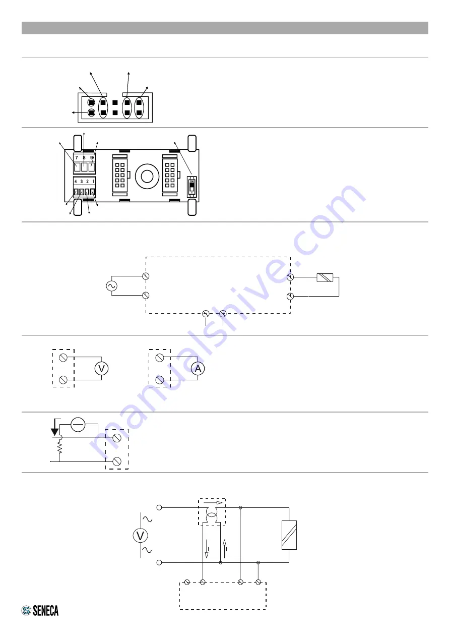
Power supply and Modbus interface are available using the Seneca DIN rail bus, via the IDC10 rear connector, or
the Z-PC-DINAL-17.5 accessory.
RS485 GND
RS485 A
RS485 B
Power Supply AC / +
Power Supply AC / -
IDC 10
1
Back connector (IDC 10)
The illustration shows the meanings of the various
IDC10 connector pins if signals are to be sent via
them directly.
Power Supply AC
Ground
Power Supply AC
GNDSHLDG
ND
CANL / B
CANL / A
DIP SWITCH
(1230 Ohm terminator)
Z-PC-DINAL2-17.5 accessory use
If the Z-PC-DINAL2-17.5 accessory is used, signals
can be sent via terminal boards. The illustration
shows the meaning of the various terminals and DIP-
switch position (found in all supports for the DIN rail
listed in Accessories) for the termination of the CAN
network (not used for the Modbus network). GNDSH-
LD:
Connection cable signal protection shield (recom-
mended).
Retransmitted input/output
The module accepts an input voltage up to 500 Vac maximum. Provide the input voltage to terminals 10 and 12
and connect terminals 7 and 9 to the load to be analyzed.
MAX
5 A rms
MAX
500 V
AC
7
9
10
12
LINE IN
LINE OUT
Z203-2
LINE
LOAD
Analogue output
The module provides a voltage output (0 - 10 Vac, 0 - 5
Vac) or current (0 - 20 mA, 4 - 20 mA).
For the electrical connections, we advise you to use
screened cables.
NB: there is no isolation between RS485 and retransmit-
ted output.
2 3
5
5
6
4
+
+
Digital output
The module provides a digital output: each pulse (dura-
tion: 200 ms) corresponds to a certain number of incre-
ments of the energy count (see the Digital Output Ratio
register). Imax=V/R=50 mA
+
6
1
+
-
I
R
V
EXAMPLE OF CONNECTION WITH EXTERNAL TA (in this case, configure the Z203-2 using the software
and NOT the dip-switches)
F
230 Vac
N
P1/K
P2/L
S1/K
S2/L
TA
Z203 -2
N.C.
7 9
10 12
LOAD
MODULE SUPPLY
Voltage output
Current output
Digital output


