background image

ENGLISH - 4/8

t

RS485

A

RS485

B

RS485

GND

IDC10

Power supply

AC-

Power supply

AC+

B

A

Don’t turn upside down

don’t force the insertion

the module and

o

into

f the IDC10 connector

the

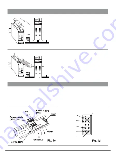
Z-PC-DIN bus. The IDC10 connector located on the rear of the module will be inserted on a free slot
of Z-PC-DIN accessory. In the figure you can see the meaning of the various pins of the rear IDC10
connector if you want to provide the signals directly through this connector. The pictures

and

Fig. 1 c

Fig.1 d

show how to connect powersupply and RS485 COM1 port to the rear IDC10 connector.

USE OF Z-PC-DINAL ACCESSORY

Insertion on the IEC EN 60715 DIN rail:

1) Move the two hooks on the back of the module
outwards as illustrated in fig. 1b.
2) Insert the module rear IDC10 connector into a free
slot of DIN rail accessory as you can see in fig 1a.
(the insertion is one way only because the connectors
are polarized).
3) To secure the module to the IEC EN 60715 DIN rail,
tighten the two hooks on the side of the IDC10 rear
connector as shown in fig. 1a.

Removal from IEC EN 60715 DIN rail:

As shown in fig. 1b:
1) Move outwards the two hooks on the side of the
module, with the help of a screwdriver.

2) Extract the module from the IEC EN 60715 DIN rail.

INSTALLATION ON AND REMOVAL FROM IEC EN 60715 DIN RAIL

Fig. 1a

20 21

19

23 24

22

11 12

10

D 4

I

D 3

I

D 2

I

DI1

ETH
LNK

ETH
ACT

SD

PWR

ETHERNET

GSM

485
ACT

DO2

D 1

O

ANTENNA

Z-GPRS3

19 20 21
22 23 24

micro

USB

10 11 12

13 14 15
16 17 18

1 2 3
4 5 6

S

SENECA

Fig. 1b

20 21

19

23 24

22

11 12

10

D 4

I

D 3

I

D 2

I

DI1

ETH
LNK

ETH
ACT

SD

PWR

ETHERNET

GSM

485
ACT

DO2

D 1

O

ANTENNA

Z-GPRS3

19 20 21
22 23 24

micro

USB

10 11 12

13 14 15
16 17 18

1 2 3
4 5 6

S

SENECA

Содержание Z-GPRS3 HW2

Страница 1: ...bed in it This informations may be modified or integrated for technical and or commercial requirements SENECA s r l Headquarters Via Austria 26 35127 PADOVA ITALY Phone 39 049 8705355 8705359 Fax 39 0...

Страница 2: ...V or 19 28 V P max C C 50 60 Hz 6 5W If the voltage is lower than 12 V the internal UPS battery can t be recharged DIGITAL INPUTS Number of channels 4 PNP or NPN configurable Input voltage OFF 4V ON...

Страница 3: ...thout any interruptions for at least 72 hours in order to charge the internal batteries Disposal of electrical electronic equipment applicable throughout the EU and other countries with separate colle...

Страница 4: ...ear IDC10 connector into a free slot of DIN rail accessory as you can see in fig 1a the insertion is one way only because the connectors are polarized 3 To secure the module to the IEC EN 60715 DIN ra...

Страница 5: ...r between 19 and 28 V C A The power supply source must be protected from any malfunctions of the module through appropriately sized safety fuse 2 ANALOG INPUTS Voltage Current active sensor 4 fili Cur...

Страница 6: ...e not used Fast Blinking 0 2s ON 0 2s OFF n o nononononononono RS485 or RS232 communication Timeout GSM Yellow Blinking 64ms ON 3s OFF n o noooooooooooooooooooooooo Connected to the GSM network Blinki...

Страница 7: ...ct 4 PWR STS Green ON n Z GPRS3 ON inactive log status ready Slow Blinking 2 8 sec ON 0 4 sec OFF nnnnnnnnnnnnnnoo Z GPRS3 active log status normal Slow Blinking 1 6 sec ON 1 6 sec OFF nnnnnnnnooooooo...

Страница 8: ...I D 3 I D 2 I DI1 ETH LNK ETH ACT SD PWR ETHERNET ANTENNA Z GPRS3 19 20 21 22 23 24 micro USB micro USB 10 11 12 13 14 15 16 17 18 1 2 3 4 5 6 S SENECA ETH USB GSM 485 ACT DO2 D 1 O The module has a R...

Отзывы: