background image


DT-E 1.4: SUN PROTECTION SCREEN – VENETIAN BLINDS Z90                                                                                                                                                                           
Issue 2 / April 2017 / EN                                                                                                                                                                                


        page  53 / 58                                                                                                                                                      


6.


SYSTEM USE AND MAINTENANCE 

6.1.


USING THE PRODUCT IN ACCORDANCE WITH ITS  INTENDED USE  

The  system  should  be  used  in  accordance  with  its  intended  use  determined  by  the  manufacturer.  If  the  system  is 
used  and  modified  in  a  manner  different  from  the  one  described  within  this  documentation,  the  system  is  used 
incorrectly. Introducing arbitrary changes influencing safe operation of the product is not acceptable.  
 
The following counts as proper product use: 


regular or predictable use which does not include, e.g. risk undertaken deliberately or consciously by the user, 


applying admissible values of work parameters, 


observing recommendations for use, 


carrying out periodic product inspections and maintenance, 


following the requirements determined in the item ‘Supervision of Safe Product Use’, 


data included in the item ‘Technical Specifications’. 

 
In case of improper use: 


the product can pose threat to its operators, 


the product shall be exposed to damage, 


it can be of negative influence on its functionality, 


do not use the product in the course of maintenance work (e.g. window cleaning). 

6.2.


INSTRUCTIONS FOR NON -PROFESSIONALS  

 
Prior to beginning to use the product this documentation should be carefully read. 
 
Non-professionals  shall denote people who are assigned  by the  Buyer to carry out activities connected with routine use, 
cleanness and maintenance of the product. 
Being familiar with this documentation guarantees fault-free operation of the product. 
 
List of activities that can be carried out by non-professionals: 


routine operation: 
- carrying out activities which do not influence work parameters of the product, 
- switching on and off by pressing control buttons, 


product maintenance and cleanness described in the further part of this documentation. 

6.3.


TECHNICAL INSPECTION, MAINTENANCE AND RE PAIRS 

 
It is recommended to conduct periodic technical inspections of the product carried out by specialised service crews.  
The  inspections  consist  in  checking  product  operation,  mechanism  adjustment,  and  exchange  of  wear  parts.  Routine 
maintenance is carried out by the User themselves. Product maintenance should be performed at least once (1) a year by 
specialised service crews. 
The inspections are provided against payment. 


Basic activities carried out during a periodic inspection: 


Verification of: 


product mounting to the structural elements, 


technical condition of the movable elements of the product, 


condition of electrical cables and inspection of their connection to the electrical system, 


tension of cable guides and their correction if necessary, 


screw and rivet connections, 


 technical condition of the slats, guides and seals, 


 mounting of the product drive mechanism (motor, gear), 


effectiveness of operation of the residual current device. 


Possibly adjusting and improving the mounting of the changed sub-assembly. 

Содержание Venetian Blind Z90

Страница 1: ...1 Sun protection screen Venetian Blind 1 4 Venetian Blind Z90 TECHNICAL AND OPERATIONAL DOCUMENTATION INSTALLATION AND OPERATING MANUAL AND INSTRUCTIONS FOR SAFE USE 1 4 DT E DTE DT E...

Страница 2: ...Wschodnia 23A Plant address Wydzia aluzji Fasadowych i Refleksoli Fa ade and External Textile Roller Blind Department 45 449 Opole ul Wschodnia 23A Contact details Tel 48 77 553 21 00 sekretariat Fax...

Страница 3: ...upporting product 15 4 5 3 Installation of venetian blind Z90 with cube and oval guide rail group installation 21 4 5 4 Concealed guide rail installation 30 4 5 5 Window frame guide rail installation...

Страница 4: ...124 Linked documents Declaration of performance Declaration of conformity product with motor and manual of installation and use of motors and control 1 2 NOTES ON SYMBOLS AND MARKS The below symbols i...

Страница 5: ...MATION REGARDING SAFETY WARNING FOLLOWING THE MANUAL IS ESSENTIAL FOR SAFETY OF PEOPLE KEEP THIS MANUAL The documentation is valid jointly with the information concerning a specific product which is a...

Страница 6: ...on 0 4 to 1 A depending on the motor type and blind size protection level IP 44 IP 54 depending on the motor type time of continuous work 4 to 6 mins depending on the motor type torque 6 Nm 20 Nm depe...

Страница 7: ...connected with work of mechanical parts caused by electric drive during its work is not said to be a significant danger and it is a way of comfort the level of acoustic pressure is up to 58dB the moto...

Страница 8: ...NS OF PRODUCT TRNAPORT AND STORAGE List The product is factory packed in a cardboard box to prevent its damage during storage transport and during its transportation to the place of final assembly For...

Страница 9: ...nt for the drive operation should be immobilized 4 1 REQUIREMENTS FOR SAFE INSTALLATION AT HEIGHTS Installation of the product because it requires performing work at heights is particularly dangerous...

Страница 10: ...ces making reactions with the product is forbidden Improper installation may cause hazardous situation for the user 4 4 INSTALLATION TOOLS List drills for metal and concrete hummer drill ladder scaffo...

Страница 11: ...sue 2 April 2017 EN page 11 58 Img 1 Rys 2 1 Put silencing cap on the auxiliary bracket Standard head rail bracket Elastic head rail bracket 2 Connect head rail bracket with main bracket Fit the compl...

Страница 12: ...stalled cover panels and brackets correct if necessary Appropriate leveling of the product is necessary for its correct functioning Img 4 6 Loosen the screw of elastic bracket so that it is easy to op...

Страница 13: ...modular installation Single and double guide rail bracket types Type 1 standard Type 2 Type 3 Type 4 Type 4 installation manner Loosen the cone shaped screw so that the bracket is easy to click into...

Страница 14: ...NDS Z90 Issue 2 April 2017 EN page 14 58 11 Slide brackets to guide rails Install brackets to guide rails by fixing the screw Img 9 Img 10 12 Slide the guide rail on the slat pins Img 11 13 Set the ve...

Страница 15: ...guide rail axis then secure the bracket Img 14 Img 15 16 Install guide rail end caps 1 set screw After the installation is finished set the end positions and check the correct functioning of the blind...

Страница 16: ...ing should be performed with a wrench 10 and maximum 4 full turns 1440 NOTE bigger turn will result in tearing out the threaded stud 1 Measure and mark the spots for guide rail brackets installation I...

Страница 17: ...DT E 1 4 SUN PROTECTION SCREEN VENETIAN BLINDS Z90 Issue 2 April 2017 EN page 17 58 Img 3 Img 4 Img 5 Img 6 Img 7 Img 8 3 Loosen cone shaped screws securing the bolts Img 9...

Страница 18: ...17 EN page 18 58 4 Pull the bolt out Img 10 5 Slide the guide rails on brackets and secure the cone shaped screw Img 11 12 and 13 Img 11 Img 12 Img 13 6 Check the vertical level of the guide rail Img...

Страница 19: ...to flat bars placed in the cassette brackets should be placed in the axis of the cassette Img 16 10 Loosen the installation flat bar on the cassette side Img 17 11 Connect the cassette with guide rail...

Страница 20: ...It is necessary for correct functioning of the product Img 21 13 Install top end caps in the guide rails Img 22 14 Put the head rail with bundle into the guide rails so that the label strona od okna...

Страница 21: ...Img 25 16 Install the head rail with bundle to open head rail brackets Close the bracket and tighten the screws Img 26 17 Install bottom guide rail end caps Img 28 18 Check the functioning of the bli...

Страница 22: ...SCREEN VENETIAN BLINDS Z90 Issue 2 April 2017 EN page 22 58 Img 1 Img 2 Img 3 2 Install the bracket to facade with appropriate fixing system Img 4 3 Measure and mark the installation spot of the secon...

Страница 23: ...ssue 2 April 2017 EN page 23 58 Img 6 4 Install the second bracket Img 7 5 Measure and mark the installation spot of the next bracket img 8 install the bracket img 7 Img 8 6 Check the vertical level o...

Страница 24: ...sure and mark the installation place of the second guide rail Img 10 11 Img 10 Img 11 8 Install the next bracket img 12 9 Measurement and marking for the following brackets should be done similarly to...

Страница 25: ...ical level of installed brackets Img 14 12 Loosen cone shaped screws securing the bolts and pull the bolts out Img 15 Img 16 13 Slide the guide rails on bracket bolts img 17 settle the guide rail img...

Страница 26: ...7 EN page 26 58 Img 18 Img 19 14 Check the level of installed guide rails Img 20 15 Loosen the installation flat bar in the cassette so that it can be slide on the guide rails Img 21 16 Install to the...

Страница 27: ...N SCREEN VENETIAN BLINDS Z90 Issue 2 April 2017 EN page 27 58 17 Put the cassette on guide rails Img 23 18 Check the vertical and horizontal level of the cassette Img 24 25 Img 24 Img 25 19 Tighten th...

Страница 28: ...Install the middle guide rail Img 27 21 Insert the head rail with bundle to the guides Img 28 and 29 Img 28 22 Put the head rail with bundle into the open brackets so that the label strona od okna fa...

Страница 29: ...2 April 2017 EN page 29 58 24 Install consecutive bundles to brackets Img 31 25 Slide the cover profile to external guides Img 32 and cut the excess Img 33 Img 32 Img 33 26 Put the guide rails end cap...

Страница 30: ...ng of the blind and set end positions according to the motor manual 4 5 4 CONCEALED GUIDE RAIL INSTALLATION a Guidelines for installation Application of concealed side guides is especially recommended...

Страница 31: ...to the blind In case of the base not being stable enough it is necessary to provide supporting substructure that will provide stability and correct profile alignment Profiles must be mounted parallel...

Страница 32: ...INDS Z90 Issue 2 April 2017 EN page 32 58 Fig 2 Installation of mounting profile in window niche Fig 3 Positioning of the mounting profile in window niche 1 Mounting profile 2 Concealed guide rail 3 G...

Страница 33: ...res determining of how the blinds are divided The division line is located in axis of the double side guide Blinds are shown in Fig 3b and 3c For each blind group of blinds it is necessary to take min...

Страница 34: ...unting profile and fastening them with tapping self drilling screws you must remove gaskets from the side guide and protect them against damage Then reinstall them b Installation 1 Fix head rail brack...

Страница 35: ...ll in the upper part of mounting profile using tapping or self drilling screw as shown in Fig 4 The head of the screw should not block pins in the slats Follow the step for both guide rails Attention...

Страница 36: ...the guide rail in the mounting profile pre drill holes for tapping screws to fasten guide rail Then insert the gaskets into that section The gaskets will be longer than the guide rail longer with leng...

Страница 37: ...s Guidelines for window frame guide rail installation Length of the guide rail profile equals height of the system 50 mm Fig 6a shows window frame installation Fig 6b shows niche installation Installa...

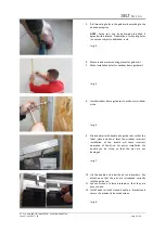
Страница 38: ...height and secure tightly Img 1 b Installation 1 Connect head rail bracket to the main bracket Measure to the cover panel adjust and secure tightly Img 1 NOTE For installation on window frame in the r...

Страница 39: ...tall window frame guide rail to window or window niche Img 6 9 Slide head rail with bundle into guide rails so that the label strona od okna faces the window Incorrect installation of the bundle will...

Страница 40: ...d fig 8 profile should be aligned with the upper Edge of guide rail Img 9 NOTE Pay particular attention so that during guiding profile installation it is not damaged by pins Fig 8 14 Place profile on...

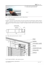
Страница 41: ...of system with under plaster cassette is advised for the installation of Venetian Blind on facades with thermal insulation Under plaster cassette limits the effect of thermal bridge and provides aesth...

Страница 42: ...tallation Fig 12b shows niche installation Installation of the guide rail must be fixed to the base as well as it should be linear and perpendicular to Venetian Blind Guide rail profiles must be insta...

Страница 43: ...ed to use washers with bigger outer diameter for the installation of the under plaster cassette to avoid deformations of the cassette Under plaster cassette is delivered without hole for feeder cable...

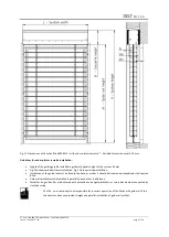
Страница 44: ...ssette variable dimension usually 30 mm Fig 14 Scheme of preparation of the installation holes in the guide rail profiles b Installation 1 Measure and mark places for installation holes for the under...

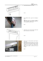
Страница 45: ...g holes is a service subject to additional costs Img 2 7 Install guide rail to the under plaster cassette and fasten it to the base or subconstruction Fig 17 8 Loosen screws of elastic brackets so tha...

Страница 46: ...guide rail 11 Install head rail with closed bundle in bracket and secure the previously loosened screws Img 4 12 Place guiding profile inside the guide rail according to Img 5 and Fig 18 Img 5 NOTE P...

Страница 47: ...ssette Fig 19 15 Connect feeder cable to the Venetian Blind and check the correctness of system functioning and setting end positions Correct if necessary NOTE Connection of the feeder cable should be...

Страница 48: ...aunas rooms for domestic animals operating theatres in hospitals pump rooms heat exchange rooms spaces limited by conducing areas campsites open spaces etc are regarded as environments with increased...

Страница 49: ...y the thermal protection appropriate time should pass before turning on again depending on the type of engine and atmospheric conditions about 16 minutes 4 6 3 MANUAL DRIVE Opening closing and setting...

Страница 50: ...to read them It is forbidden to introduce modification in the electrical design or in the equipment configuration without consulting the manufacturer or an authorised representative Before the product...

Страница 51: ...nal documentation No sharp objects or protruding elements which can hook the bottom bar or slats can be kept near the system it is forbidden to use faulty or incomplete product e g without a switch ti...

Страница 52: ...handing it over to operation post assembly check in another place b make sure that the product exposed to conditions causing degradation of its technical condition which may bring about dangerous situ...

Страница 53: ...the Buyer to carry out activities connected with routine use cleanness and maintenance of the product Being familiar with this documentation guarantees fault free operation of the product List of acti...

Страница 54: ...conditions proximity of thoroughfare construction works carried nearby and environmental pollution It is recommended to clean slight dirt of metal aluminum surfaces with the use of water with delicate...

Страница 55: ...ation cleaning and lubrication Electrical devices delivered to the Supplier in a manner not allowing for operation check e g cut off motor cable receiver in parts Damages resulting from incorrect inst...

Страница 56: ...tailed description of the defect the name of the company which assembled the product and the date of finding out the defect Product with no invoice number order or contract number will be considered a...

Страница 57: ...effect on the environment and human health No Subject European legal basis Polish legal basis 1 Waste electrical and electronic equipment Directive 2012 19 EU of the European Parliament and of the Co...

Страница 58: ...A 2006 42 EC a Marking on the accompanying documents SELT Sp z o o Opole ul Wschodnia 23A POLAND 12 EN 13659 Venetian Blinds Z90H 450x200 Venetian Blinds Z90H 180x500 For external use Wind load resist...

Отзывы: