4.1
/ Installation of the overfill prevention device
IMPORTANT: Protect the overfill prevention device against impurities such as sand during fitting!
1
:
We recommend positioning the overfill prevention device on the longitudinal axis of the tank.
2
:
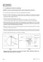
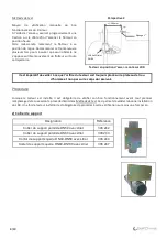
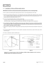
Mount the overfill prevention device on the pipe sleeve under the manhole plate placing the float under
the
tester. The 50mm minimum distance between the top of the overfill prevention device and the tank
generator
must be respected in all circumstances. (Figure 2)
3
:
Connect the pipe (position 2/Figure 1) to the overfill value:
-
measure distance X between the manhole (position 1/Figure 1) and the tank bottom.
-
shorten the pipe to leave a space of 70 mm between the bottom of the pipe and the tank bottom.
4
: To confirm the earthing of the overfill prevention device when fitting it in the tank, check that the
potentials
of the manhole pipe sleeve and the pipe situated at the bottom of the overfill prevention
device are the same.
A test of electric continuity must be carried out.
5
:
Replace the manhole plate after fitting the filler pipe and check that the float cannot rub against the
internal
pipes.
6
:
Check the diameter of the tank vent. Its cross-section should be at least equal to a quarter of the cross section
of the filler pipe.
7
:
Fit the manufacturer’s plate in the filler pipe.
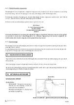
Figure 1
Figure 2
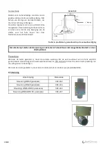
Caution: Do not make any pressure test of tank
below – 30 kPa or above +100 kPa
in order to avoid any
possible damage of the overfill prevention device.
IV)
FITTING
2
1
50 mm
Float
Spacer No 2
Top of manhole
Release valve
LEVEL Lmax
Counterweights
LEVEL L1
Rest position
Spacer No 1
16/40

