47
ATSEL HMI User Manual
standard instruction of the IEC61131/1 international ladder diagram. The editing mode is
similar to that of Japanese PLC.
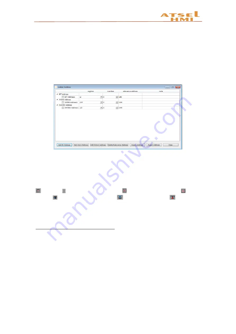
Ladder address mapping: you can add bit address, word address, double word
address. The register is the address type, number is the ladder address number, and can
write the address actual meaning information. For example, LQD0 is the register LQD+
number 0, the relevant address VD100, VD100=LQD0. You can import and export
addresses, which can be repeated in other projects.
Ladder diagram editing: the left is a ladder diagram instruction set, in the ladder
diagram editing screen, if click the instruction position which should be placed, click the
corresponding instructions, input address information, then the editing screen shows the
corresponding ladder diagram instructions. The editing method is basically same as PLC.
And, there are common instructions on the ladder menu, which can be directly clicked.
insert line, to insert structure vertical line, delete structure vertical line,
clearing
(delete),
on / off the relevant address,
import ladder diagram,
export ladder
diagram. After editing, it will automatically detect the editing correct or not. If not, it will
remind the ladder diagram transfer failure. Click confirm automatically saving the ladder
diagram project.
Note: timer instruction, timer base is 10ms.
Example
1. Project target
Design a three-person responder, when anyone of them in the first to press, the
corresponding seat lights on, the other players press then invalid, the screen shows the
name of the first player. The presenter button can turn off all the lights.


