


7.1.2 Earthing
For the protection of the users, the plant must be correctly con-
nected to the earth. The power supply lead is provided with a
(green and yellow) conductor for earthing, which must be con-
nected to a plug fitted with an earth connection.
7.1.3 Electric connection to the supply mains
The equipment is provided with a single electric connection with
4mmq cable positioned in the rear part of the power source.
Size table of the power source input cables and fuses:
SISTOR 82
Rated voltage
400 V ±15% - 230 V ±15%
Voltage range
340/460 V - 195/265 V
Delayed fuses
25 A 400 V - 40 A 230V
Power supply cable
4x4 mm2
* The electrical system must be made by skilled technicians
with the specific professional and technical qualifications
and in compliance with the regulations in force in the
country where the equipment is installed.
* The welding power source supply cable is provided with a
yellow/green wire that must ALWAYS be earthed. This yel-
low/green wire must NEVER be used with other voltage
conductors.
* Verity the existence of the earthing in the used plant and
the good condition of the socket/s
* lnstall only plugs that are homologated according to
the safety regulations.
8.0 CONNECTING THE EQUIPMENT COM-
PONENTS
Keep to the safety regulations contalned in section
“1.0 SAFETY”.
Connect the componente carefully, in order to
avoid power losses.
9.0 SETTING UP
For installation of the system, follow the instructions below:
1. Place the generator in a dry, clean place with suitable venti-
lation.
2. Connect up the compressed air supply with a 1/4 inch to the
air inlet P1 in the filter unit F1 (Fig.2). The pressure must
ensure at least 5 bars with a flow rate of at least 200 litres a
minute.
Securely connect the earth cable connector to the generator
as shown in figure 6.
3. Position the earthing clamp onto the piece to be cut, ensuring
that it makes a good electric connection (Fig. 6).
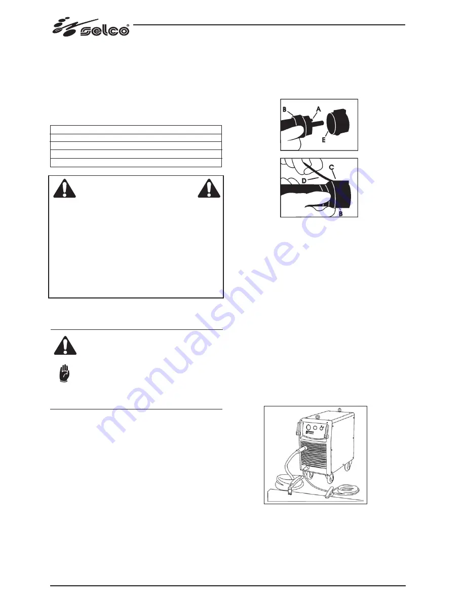
4. Check that all the components of the torch are present and
correctly fitted and connect the torch fitting to the connector
on the generator as shown in figure 5.
Insert the male fitting (torch side) into the corresponding
female fitting (machine side). Align the locating tooth (A) on
the housing and insert the ring nut (B) which must be com-
patible.
To permit screw-tightening of the ring nut (B), the tool provi-
ded (D) must be first inserted and pressed into the hole (C)
in order to release the anti-rotation lock. This operation must
be performed until the ring nut has been completely tighte-
ned. To disconnect the torch, first release the anti-rotation
lock by inserting the tool provided (D) into the hole (C).
Fig. 5
5. Switch on the system, ensuring the LED's are working cor-
rectly and some display.
If operating faults occur in the generator it will be inhibited
until normal operating conditions are restored. Press the gas
test pushbutton (T2 in Fig 1) in order to remove residual
impurities from the compressed air circuit, then lift and turn
the knob to adjust the pressure (F1 Fig.2) until the display D2
shows a pressure reading of 5 bars (carry out the operation
keeping the gas test button pressed down, so as to make the
adjustment with air circulating in the piping).
6. Set the value of the cutting current with the potentiometer,
keeping in mind the thickness to be dealt with.
7. Press for a moment the torch button so as to generate the
pilot arc; release the control, checking the machine is cor-
rectly operating with the display panel. It is advisable not to
keep the arc lit to no purpose without making contact, so as
to prevent wear on the electrode and the nozzle. If you con-
tinue to use it like this the apparatus itself will turn off the
pilot light after about 6 seconds.
In the case where a fault is found during the above phases,
check the LED's, the display and if necessary consult the
chapter "Possible electrical faults" in the manual.
Fig. 6
WARNING
16