


2.0 ELECTROMAGNETIC COMPATIBILITY (EMC)
This device is built in compliance with the indications contained in the
harmonized standard EN50199, to which the operator must refer for the
use of this apparatus.
- lnstall and use the apparatus keeping to the instructions given in
this manual.
- This device must be used for professional applications only, in
industrial environments It is important to remember that it may
be difficult to ensure the electromagnetic compatibility in other
environments.
2.1 Installation, use and area examination
- The user must be an expert in the sector and as such is responsible
for installation and use of the equipment according to the manufac-
turer's instructions.
lf any electromagnetic disturbance is noticed, the user must soave the
problem, if necessary with the manufacturer's technical assistance.
- In any case electromagnetic disturbances must be reduced until they
are not a nuisance any longer.
- Before installing this apparatus, the user must evaluate the potential
electromagnetic problems that may arise in the surrounding area, con-
sidering in particular the health conditions of the persons in the vicinity,
for example of persons fitted with pacemakers or hearing aids.
2.2 Emission reduction methods
MAINS POWER SUPPLY
- The welding power source must be connected to the supply mains
according to the manufacturer's instructions.
In case of interference, it may be necessary to take further precautions
like the filtering of the mains power supply.
lt is also necessary to consider the possibility to shield the power supply
cable.
WELDING POWER SOURCE MAINTENANCE
The welding power source needs routine maintenance according to the
manufacturer's instructions.
When the equipment is working, all the access and operating doors and
covers must be closed and fixed.
The welding power source must not be modified in any way.
WELDING AND CUTTING CABLES
The welding (cutting) cables must be kept as short as possible, positio-
ned near one another and laid at or approximately at ground level.
EQUIPOTENTIAL CONNECTION
The earth connection of all the metal componente in the welding (cut-
ting) installation and near it must be taken in consideration.
However, the metal componente connected to the work-piece will
increase the risk of electric shock for the operator, if he touches said
metal componente and the electrode at the same time.
Therefore, the operator must be insulated from all the earthed metal
componente.
The equipotential connection must be made according to the national
regulations.
EARTHING THE WORKPIECE
When the workpiece is not earthed for electrical safety reasons or due
to its size and position, the earthing of the workpiece may reduce the
emissione. It is important to remember that the earthing of the work-
piece should neither increase the risk of accidents for the operators, nor
damage other electric equipment.
The earthing must be made according to the national regulations.
SHIELDING
The selective shielding of other cables and equipment present in the
surrounding area may reduce the problems due to interference. The
shielding of the entire welding (cutting) installation can be taken in con-
sideration for special applications.
3.0 RISK ANALYSIS
13
WARNING
Risks posed by the machine
Risk of wrong installation.
Electrical risks.
Risks connected with electromagnetic disturbances produced by the
welding power source and induced on the welding power source.
Solutions adopted to pervent them
A manual with the instructions for use has been pro-
duced for this purpose.
Application of the
EN 60974-1
Standard.
Application of the
EN 50199
Standard.
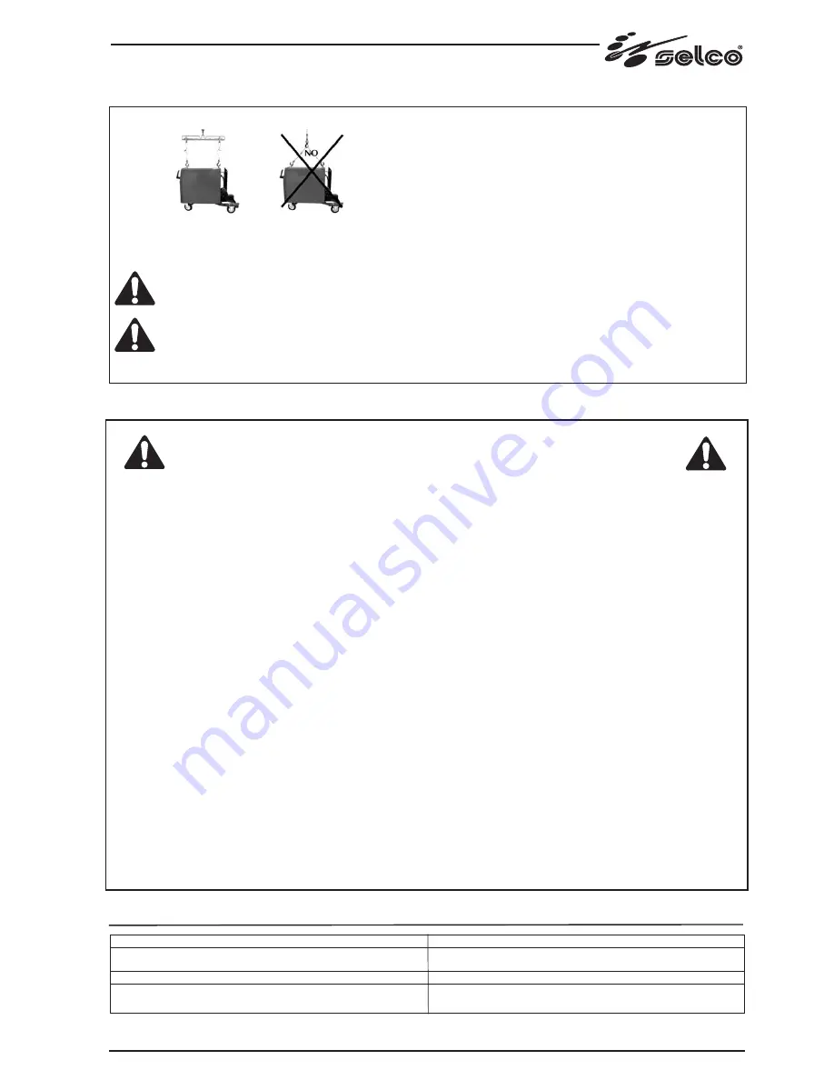
1.7 Attention: method of lifting
To correctly lift the machine, follow the diagram in Figure A.
Avoid absolutely lifting it at any angle different from 90°.
Never lift the machine in the way shown in figure B :
this could damage the eyebolts.
Be careful not to cause damage during lifting.
The manufacturer accepts no liability if the above prescription is not duly observed and complied with at all times.
Figura A
Figura B