


SEL-351R Falcon Data Sheet
Schweitzer Engineering Laboratories, Inc.
2
Functional Overview
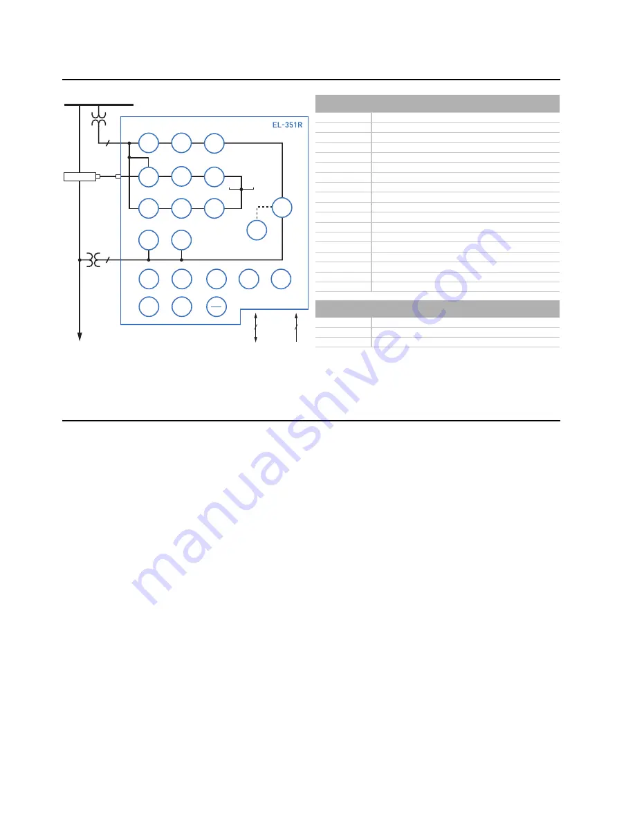
Figure 1
Functional Diagram
Functional Replacement for Traditional Recloser Control
EZ Settings for Basic
Recloser Functions
For traditional recloser functions, the SEL-351R Falcon
is easy to set. Only settings such as minimum trip pickup,
curve type, and reclose interval are necessary. These set-
tings are made at an EZ (easy) access level. SEL
OGIC
control equations cannot be changed at this access level.
Control logic is preconfigured at the factory. To
customize the logic for advanced functions, the SEL
OGIC
control equations must be reprogrammed.
Reclosing
The SEL-351R Falcon can reclose as many as four (4)
times. This allows as many as five (5) operations of any
combination of fast and delay curve overcurrent
elements. Each reclose interval can be set for as many as
999,999 cycles (more than 4.5 hours), if necessary.
After a reclose interval has timed out, the control waits a
user-set time (close power wait time) for the presence of
adequate Vac power before proceeding with the auto
reclose. The recloser needs either primary or secondary
voltage to provide the closing power, depending on how
the recloser is equipped. The Vac power into the
SEL-351R Falcon is an indication of the presence of this
primary or secondary voltage. The close power wait time
has the same 999,999-cycle setting range as the reclose
interval.
The reset times are set separately for reset timing for an
auto reclose and reset timing for a manual/remote close
from lockout. Traditionally, the reset time for a
manual/remote close from lockout is set for less than the
reset time for an auto-reclose. The reset times have the
same 999,999-cycle setting range.
Front-panel LEDs track the CONTROL STATE for
auto-reclosing:
RESET
,
CYCLE
, or
LOCKOUT
(see Figure 14
and Table 4).
Sequence coordination logic is enabled to prevent the
SEL-351R Falcon from tripping on its fast curves for
faults beyond a downstream recloser.
Customize reclosing logic by using SEL
OGIC
control
equations. Use programmable counters, latches, logic
functions, and analog compare functions to optimize
control actions.
ANSI NUMBERS/ACRONYMS AND FUNCTIONS
25
Synchronism Check*
27
Undervoltage
50N
Neutral Overcurrent
50 (P, G, Q)
Overcurrent (Phase, Ground, Neg. Seq.)
51N
Neutral Time-Overcurrent
51 (P, G, Q)
Time-Overcurrent (Phase, Ground, Neg. Seq.)
59
Overvoltage
59 (P, G, Q)
Overvoltage (Phase, Ground, Neg. Seq.)
67N
Directional Neutral Overcurrent*
67 (P, G, Q)
Directional Overcurrent (Phase, Ground, Neg. Seq.)*
79
Autoreclosing
81 (O, U)
Over-/Underfrequency
85 RIO
SEL M
IRRORED
B
ITS
®
Communications
DFR
Event Reports
HMI
Operator Interface
LGC
SEL
OGIC
®
Control Equations
MET
High-Accuracy Metering
SER Sequential
Events
Recorder
ADDITIONAL FUNCTIONS
BRM Breaker
Wear
Monitor
LDP
Load Data Profiling*
LOC
Fault Locator*
* Optional Feature
51N
50N
27
59
79
67N
50
P
G
Q
51
P
G
Q
Line
Bus
4
EIA-232
EIA-485
1
IRIG-B
R
esidual
S
3
1
27
81
O
U
59
P
G
Q
25
RECLOSER
*
*
67
P
G
Q
85
RIO
DFR
HMI
LGC
LOC
MET
SER
BRM