6
TB MRM3 07.01 E
3.1.1 Analog Inputs
The analog input signals of the phase currents I
L1
(B3 -
B4), I
L2
(B5 - B6), I
L3
(B7 - B8) and the earth current I
E
(B1 - B2) are fed to the protection device via separate
input CTs.
The current measuring quantities are galvanical de-
coupled, analogously filtered, and then fed to the ana-
log/digital converter.
3.1.2 Output Relays
The
MRM3
has 5 output relays. Two of these relays
with two change-over contacts and three relays with
one change-over contact each are used for signalling.
The protective functions can be freely allocated except
of those for the self-supervision relay.
•
Relay 1: C1, D1, E1 and C2, D2, E2
•
Relay 2: C3, D3, E3 and C4, D4, E4
•
Relay 3: C5, D5, E5
•
Relay 4: C6, D6, E6
•
Relay 5: Self-supervision C7, D7, E7
All relays are operating according to the n. o. princi-
ple with the exception of the self-supervision relay,
which operates acc. to the n. c. principle.
3.1.3 Digital Inputs
The
MRM3
has 7 digital inputs with fixed functions.
All inputs have a common reference point : Terminal
D8. (See Chapter 3.1)
No Terminal
Function
Coding
Plug
1
C8
External reset
2
2
E8
External blocking
1
3
A2
Parameter set change-
over switch
3
4
A5
External trigger for the
fault recorder
4
5
A6
Identification „Motor
Running“
7
6
A7
Ext. trigger, undelayed
6
7
A8
Ext. trigger, delayed
5
3.1.4 Low/High Range of the Digital
Inputs
The
MRM3
is equipped with a wide-range power
supply unit and hence the supply voltage is freely se-
lectable. The switching threshold of the digital inputs,
however, has to be fixed in compliance with the sup-
ply voltage. Two different switching thresholds can be
adjusted:
Range
Plug
U
not active
U
active
Low
Plugged in
<= 8V
>= 10V
High
Open
<= 60V
>= 70V
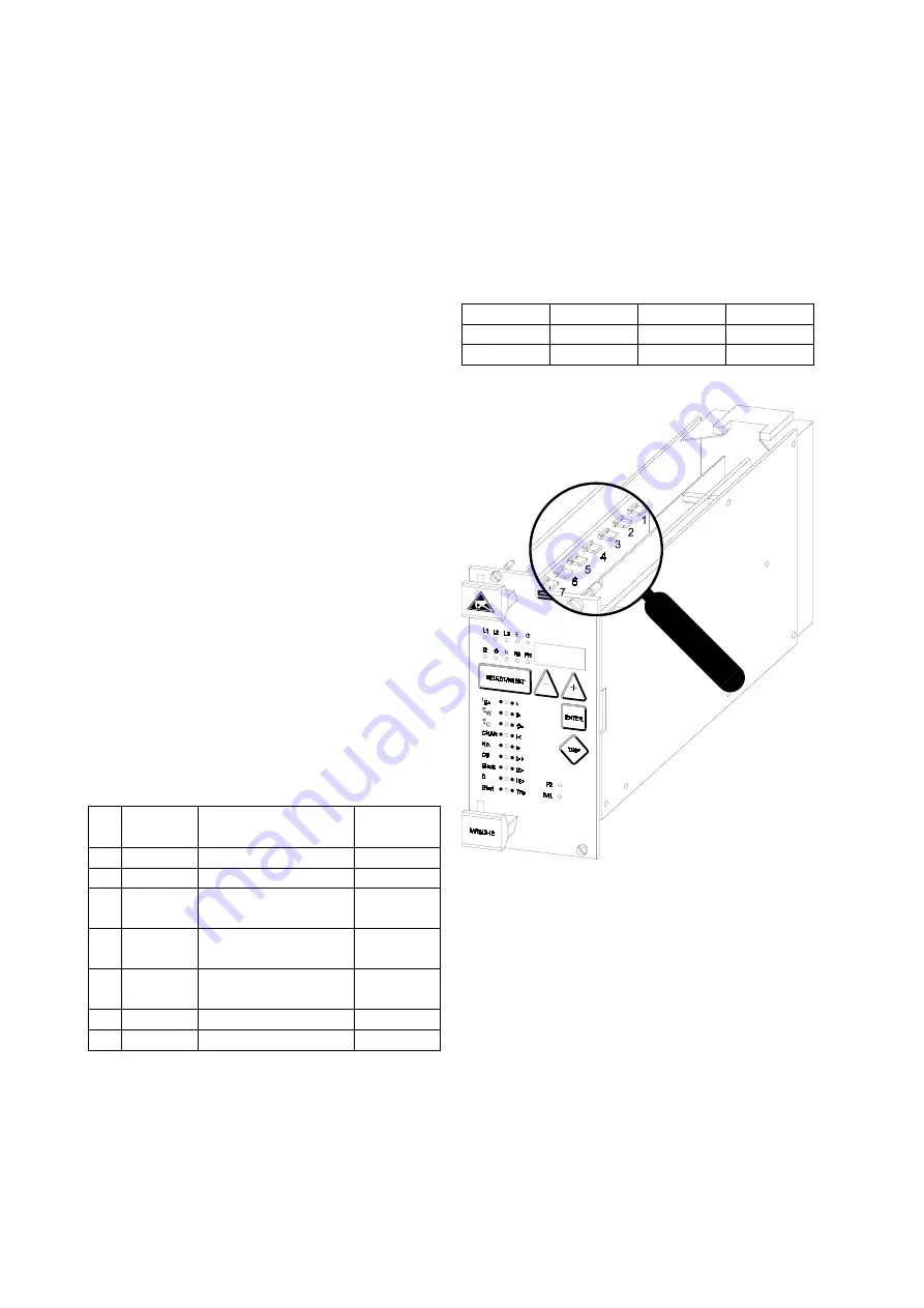
Figure 3.4
: Coding Plug
Содержание MRM3
Страница 1: ...MRM3 Motor Protection Relay ...


