6.7.
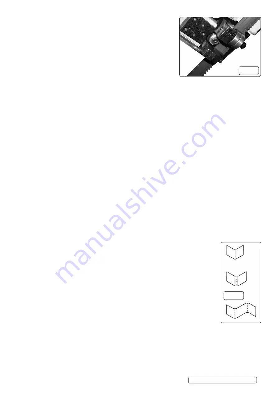
CHECKING BLADE GUIDES FIG13
6.7.1.
Check that the blade teeth are per pendicular to the base’s machined surface.
6.7.2.
Spread the blade guides as far apart as possible.
6.7.3.
Check that vice jaws are parallel and set for 90° cutoff.
6.7.4.
Position the vice jaws to have the maximum separation that will not interfere with the
blade guides.
6.7.5.
With the head in horizontal position use a square against face of rear vice jaw and
check that jaw is 90° to the side of blade.
6.7.6.
Check that the blade is in line with drive and tracking wheels.
6.7.7.
Raise the head.
6.7.8.
Look straight on at the cutting edge of the blade.
6.7.9.
Make sure that the blade sides are parallel to the sides of the bearings.
6.7.10.
Make sure the bearings touch the blades and can still be rotated by hand.
6.7.11.
Maintain eccentric shaft position and tighten socket head bolt.
6.8.
CHECKING THRUST BEARINGS
6.8.1.
The thrust bearings should be .003-.005” (average thickness of a piece of paper) away from back of blade.
6.8.2.
The thrust bearings are adjusted by moving the guide bracket.
6.9.
ADJUSTING GUIDE BRACKETS
6.9.1.
If the bearings are positioned properly and the blade is not square, one or both blade guide brackets must be adjusted.
6.9.2.
Loosen the socket head bolts.
6.9.3.
Adjust the bracket to the correct position.
6.9.4.
Tighten the socket head bolt.
6.9.5.
Check the guide bearings. Repositioning the blade guide bracket can alter the previous adjustments. Re-adjust if necessary.
6.10.
BLADE SELECTION
6.10.1. Using the proper blade is important for setting up the correct cutting conditions. Blades are made differently depending on the specific
application intended for the blade. Some simple rules can still be applied to almost all blades.
6.10.2.
A
lways remember to have at least three teeth in contact with the work during a cut. When three teeth are in contact, the blade cannot
straddle the work. This prevents a tooth that enters the cut from encountering more material than it can remove.
6.10.3. “Shocking” occurs when blade teeth contact too much material. This can strip the teeth from the blade. When cutting harder materials,
the suggested minimum number of teeth in contact is six because “shocking” on harder materials has a more detrimental effect on the
blade. Optimum number of teeth in contact with workpiece distributes blade forces among more teeth to increase cutting efficiency and
reduces blade wear.
6.10.4.
O
ptimum range is from 6-12 teeth in contact for soft materials, up to 12-24 teeth in contact for harder materials.
6.10.5.
Always have maximum number of teeth in contact with work to prevent gullets of teeth from being clogged.
6.10.6. When choosing a blade, overall size of the work is not as important as the thickness average. Thickness average is the average width
of material which blade will contact during each cut.
6.10.7.
Thickness average should be used when choosing a blade for the optimum number of teeth in contact, however, the three teeth rule
should be applied to the minimum thickness, not thickness average.
6.10.8.
K
eeping a selection of sharp blades on hand will yield better cuts. Blades may last longer because they are less likely to be misused
when proper blade is available.
6.10.9.
E
very band saw should have at least one replacement blade of each type used. Blade breakage is unpredictable. Consult a blade
manufacturer for detailed information about available blades for specific uses.
6.11.
TRACKING
6.11.1.
P
roper tracking is achieved when the drive wheel and tracking wheel are aligned. A blade that is not tracking correctly can come off the
blade wheels. Although adjustment is rarely required, tracking should be checked frequently.
CAUTION
Turn motor off and, disconnect power to check tracking.
6.12.
CHECK TRACKING
6.12.1.
Prop open the blade wheel covers.
6.12.2.
Insert a piece of paper between the blade and the lower portion of the tracking wheel.
6.12.3.
Open the pulley cover and rotate the blade by turning the motor pulley.
6.12.4.
Let the blade grab the paper. Rotate the pulley so the paper goes around the wheel.
6.12.5.
R
efer to Figure 14 to determine if an adjustment is needed.
6.12.6.
A sharp fold indicates proper tracking.
6.12.7.
C
ut or ripped paper indicates that the blade is riding against the flange of the wheel. Adjusting bolt needs
to be turned counter clockwise.
6.12.8.
N
o fold indicates the blade will ride off the wheel. Adjusting bolt should be turned clockwise.
6.13.
BLADE SPEED
6.13.1.
Choosing the proper blade speed is important for extending the life of the blade. The speed determines the
available cutting force.
6.13.2.
Harder materials require more force and are cut at a slower speed.
6.13.3.
Softer materials are cut with less force at higher speeds to ensure the proper removal of the chips.
6.13.4.
The speed and corresponding force are related to the power supplied to the blade. Four speeds are available.
6.13.5.
If a motor, other than the one sup plied is used, the cutting conditions will be changed. Four speeds are
available.
6.13.6.
S
peed is changed by moving V-Belt to one of the four pulley positions.
6.14.
CHANGING BELT POSITION
6.14.1.
Remove knob from pulley cover.
6.14.2.
Open pulley cover. Loosen socket head bolt.
6.14.3.
Move the belt to the desired position.
6.14.4.
T
ighten the socket head bolt to tension the belt. Belt is tensioned properly when a moderate pressure applied to the belt between the
pulleys produces a 1/2” of deflection.
6.14.5.
Secure pulley cover with knob.
fig.13
fig.14
Original Language Version
© Jack Sealey Limited
S
M353CE.V3 Issue 1 23/01/20


