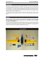
background image

FAIR CHILD PT 19.


     Instruction Manual.

4


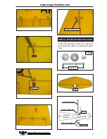
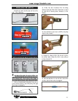
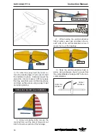
8) After both ailerons  are securely hinged,

firmly grasp the wing panel and aileron to
make sure the hinges are securely glued and
cannot be pulled out. Do this by carefully
applying medium pressure, trying to separate
the aileron  from the wing panel. Use caution
not to crush the wing structure.


7) Repeat this process with the other wing

panel, securely hinging the aileron in place.


6) Using C/A remover/debonder and a

paper towel, remove any excess C/A glue that
may have accumulated on the wing or in the
aileron hinge area.


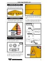
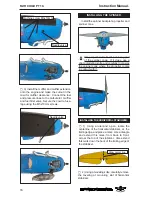
5) Turn the wing panel over and deflect the

aileron in the opposite direction from the
opposite side. Apply thin C/A glue to each
hinge, making sure that the C/A penetrates into
both the aileron and wing panel.

Work the aileron up and down several
times to “work in” the hinges and
check for proper movement.
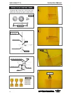
Note:


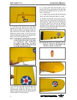
4) Deflect the aileron and completely

saturate each hinge with thin C/A glue. The
ailerons front surface should lightly contact the
wing during this procedure. Ideally, when the
hinges are glued in place, a 1/64” gap or less
will be maintained throughout the lengh of the
aileron to the wing panel hinge line.

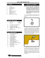
The hinge is constructed of a special
material that allows the C/A to wick
or penetrate and distribute
throughout the hinge, securely
bonding it to the wood structure of
the wing panel and aileron.

Note:

Hinge.

Содержание Fair Child PT19

Страница 1: ...notice MS 136 ASSEMBLY MANUAL Specifications Wingspan 80 5in 204 5cm Wingarea 965 7sq in 62 3sqdm Weight 11 9lbs 5 4kg Length 58 6in 148 8cm Engine 0 91 1 2cu in 2 stroke 0 91 1 2cu in 4 stroke Radio 5channelswith8 servos Speing landing gear included ...

Страница 2: ... manual is designed to help you build a great flying aeroplane Please read this manual thoroughly before starting assembly of your PT 19 Use the parts listing below to identify all parts WARNING Please be aware that this aeroplane is not a toy and if it is assembled or used incorrectly it will cause injury to people or property WHEN YOU FLY THIS AEROPLANE YOU ASSUME ALL RISK RESPONSIBILITY If you ...

Страница 3: ...he steps that follow using a high quality thin C A glue 2 Remove each hinge from the wing panel and aileron and place a T pin in the center of each hinge Slide each hinge into the aileron until the T pin is snug against the aileron This will help ensure an equal amount of hinge is on either side of the hinge line when the aileron is mounted to the wing panel HINGING THE AILERONS Note 1 Carefully r...

Страница 4: ...d deflect the aileron in the opposite direction from the opposite side Apply thin C A glue to each hinge making sure that the C A penetrates into both the aileron and wing panel Work the aileron up and down several times to work in the hinges and check for proper movement Note 4 Deflect the aileron and completely saturate each hinge with thin C A glue The ailerons front surface should lightly cont...

Страница 5: ...arden the threads and prevent the crews from pulling loose 4 Thread a control horn end with aluminum washer lock nut until the top edge of the end is 18mm from the vase of the horn as shown 3mm HINGING THE RUDDER Glue the rudder hinges in place using the same techniques used to hinge the ailerons Hinge HINGING THE ELEVATOR Glue the elevator hinges in place using the same techniques used to hinge t...

Страница 6: ...g the same method as same as the aileron control horns INSTALL FLAP CONTROL HORN 2 sets 3x30mm Aluminum Washer CONTROLHORN M3 SCREW M3 LOCK NUT Epoxy Aluminum Washer Flap CONTROLHORNM3SCREW M3 lock nut ALUMINUMWASHER 18mm ALUMINUM WASHER Epoxy Epoxy Flap M2x6mm M2x6mm Screw ...

Страница 7: ...stall the elevator control horn using the same method as same as the aileron control horns INSTALL ELEVATOR CONTROL HORN 2 sets 3x35mm Aluminum Washer CONTROL HORN M3 M3 LOCK NUT Epoxy Aluminum Washer Horizontal Stabilizer Elevator M2x6mm Screw 1 5mm ...

Страница 8: ...ts and four 4mm washers to attach the engine mount rails to the firewall Tighten the screws Make sure to use threadlock on the screws to help prevent them from vibrating loose 4x30mm INSTALL RUDDER CONTROL HORN 3mm Repeat steps to install the rudder control horn as same as steps done for ailerons Rudder control horn Elevator control horn vetical fin 18mm Epoxy Horizontal Stabilizer Elevator ...

Страница 9: ...icon fuel line Connect one end of the line to the weighted fuel pick up and the other end to the nylon pick up tube 5 With the stopper assembly in place the weighted pick up should rest away from the rear of the tank and move freely inside the tank The top of the vent tube should rest just below the top of the tank It should not touch the top of the tank 6 When satisfied with the alignment of the ...

Страница 10: ...dio system Because the size of servos differ you may need to adjust the size of the precut open ing in the mount The notch in the sides of the mount allow the servo lead to pass through Throttle servo Elevator servo Rudder servo 7 Slide the fuel tank into the fuselage Guide the lines from the tank through the hole in the firewall Fuel tank Epoxy Fuel tank 8 Use plywood template to hold in place th...

Страница 11: ...r you may need to adjust the size of the precut open ing in the mount The notch in the sides of the mount allow the servo lead to pass through String Small weight 2 Place the servo between the mounting blocks and space it from the hatch Use a pencil to mark the mounting hole locations on the blocks 3 Use drill bit in a pin vise to drill the mouting holes in the blocks 5 Use dental floss to secure ...

Страница 12: ...Manual 12 6 Secure the servo to the aileron hatch using Phillips screwdriver and the screws provided with the servo 7 Apply 1 2 drops of thin C A to each of the mounting tabs Allow the C A to cure without using accelerator C A glue ...

Страница 13: ...vo Aileron servo Wing rib Small weight String 8 A string has been provided in the wing to pull the aileron lead through to the wing root Remove the string from the wing at the servo location and use the tape to attach it to the servo extension lead Pull the lead through the wing and remove the string Flap servo Aileron servo ...

Страница 14: ...he pushrod tube in the firewall and guide it through the fuel tank mount Use medium C A to glue the tube to the firewall and the fuel tank mount 6 Connect the Z bend in the 450mm throttle pushrod to the outer hole of the carburetor arm 2 Use a pin drill and 4mm drill bit to drill a small indentation in the mount for the engine mounting screw 3 Use a drill to drill the four holes in the engine moun...

Страница 15: ... Trim and cut Because of the size of the cowl it may be nec essary to use a needle valve extension for the high speed needle valve Make this out of suf ficient length 1 5mm wire and install it into the end of the needle valve Secure the wire in place by tightening the set screw in the side of the needle valve 2 While keeping the back edge of the cowl flush with the marks align the front of the cow...

Страница 16: ...HORIZONTAL STABILIZER Draw center line 1 Using a ruler and a pen locate the centerline of the horizontal stabilizer at the trailing edge and place a mark Use a triangle and extend this mark from back to front across the top of the stabilizer Also extend this mark down the back of the trailing edge of the stabilizer Machine screw M3x10mm Needle valve 3 Install the muffler and muffler extension onto...

Страница 17: ...sfied with the align ment hold the stabilizer in place with T pins or masking tape but do not glue at this time Pen 7 Remove the stabilizer Using the lines you just drew as a guide carefully remove the covering from between them using a model ing knife Remove the covering Epoxy 8 Using a modeling knife carefully re move the covering that overlaps the stabilizer mounting platform sides in the fusel...

Страница 18: ... on each side of the vertical stabilizer where it meets the top of the fuselage Fill epoxy INSTALLING THE VERTICAL STABILIZER 1 Using a modeling knife remove the covering from over the precut hinge slot cut into the lower rear portion of the fuselage Fill epoxy 10 After the epoxy has fully cured re move the masking tape or T pins used to hold the stabilizer in place Carefully inspect the glue join...

Страница 19: ...epoxy to the bot tom and top edges of the filler block and to the lower hinge also Set the stabilizer in place and realign Double check all of your measure ments once more before the epoxy cures Hold the stabilizer in place with T pins or masking tape and remove any excess epoxy using a paper towel and rubbing alcohol Allow the ep oxy to fully cure before proceeding AILERON PUSHROD HORN INSTALLATI...

Страница 20: ...3 4 5 6 7 INSTALLING TEXTURED LANDING GEAR 4 3 5 1 2 INSTALLING THE FLAP PUSHROD M2 lock nut Wing Flap Repeat the procedure for the aileron pushrod Wing Aileron M3 lock nut 8 Repeat the procedure for the other aileron servo Aileron Wing Aileron ...

Страница 21: ...21 www seagullmodels com 6 3 7 1 2 4 7 M3x25mm Pen 2mm 2mm 6 M3x10mm Screw ...

Страница 22: ...e clevis and M2 lock nut on to each elevator control rod Thread the horns on until they are flush with the ends of the con trol rods 1 Install the elevator control horn using the same method as with the aileron control horns 2 Position the elevator control horn on the both side of elevator M3 lock nut M3 clevis 85mm 115mm Elevator control horn Rudder control horn Epoxy Epoxy Elevator control horn ...

Страница 23: ...23 www seagullmodels com Elevator pushrod MOUNTING THE TAIL WHEEL A C A glue A 1 2 3 4 6 5 1 2 M3x25mm 4 6 5 3 M3x25mm M3x25mm ...

Страница 24: ...FAIR CHILD PT 19 Instruction Manual 24 INSTALLATION PILOT AND CANOPY 2 1 3 1 Locate items necessary to install pilot cockpit panel and canopy 4 Screw C A glue ...

Страница 25: ... pilot figure on the canopy floor as show Locate the oval shaped on the canopy floor and remove the covering Use epoxy to glue this into the base of the pilot figure and glue the cockpit panel in place with C A glue please see pictures as shown If you are going to install a pilot figure please use a sanding bar to sand the base of the figure so that it is flat INSTALL THE PLASTIC PARTS 2 3 4 1 1 6...

Страница 26: ...tube Attach the aluminium tube into fuselage Insert two wing panels as pictures below Battery C A glue C A glue C A glue APPLY THE DECALS 1 If all the decals are precut and ready to stick Please be certain the model is clean and free from oily fingerprints and dust Position decal on the model where desired using the photos on the box and aid in their location 2 If all the decals are not precut ple...

Страница 27: ...balance point 110mm With the wing attached to the fuselage all parts of the model installed ready to fly and empty fuel tanks hold the model at the marked balance point with the stabilizer level Lift the model If the tail drops when you lift the model is tail heavy and you must add weight to the nose If the nose drops it is nose heavy and you must add weight to the tail to balance Accurately mark ...

Страница 28: ...does not flip the servo re versing switch on your transmitter to change the direction E From behind the airplane look at the aileron on the right wing half Move the aileron stick to the right The right aileron should move up and the other aileron should move down If it does not flip the servo re versing switch on your transmitter to change the direction C Check the rudder Looking from behind the a...

Отзывы: