


17
www.seagullmodels.com
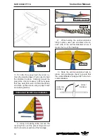
Remove the covering.
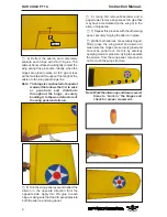
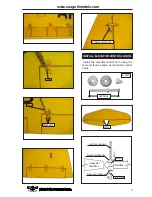
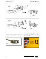
6) With the stabilizer held firmly in place,
use a pen and draw lines onto the stabilizer
where it and the fuselage sides meet. Do this
on both the right and left sides and top and
bottom of the stabilizer.
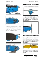
4) Install the stabilizer onto the fuselage.
Align the centerline drawn on the top and the
rear of the stabilizer with the centre of the fu-
selage. When that is aligned, hold the stabi-
lizer in that position using T-pins or masking
tape. Align the horizontal stabilizer with the
wing. When viewed from the rear, the hori-
zontal stabilizer should be level with the wing.
If it is not level, use sandpaper and sand down
the high side of the stabilizer mounting plat-
form until the proper alignment is achieved.
The tips of the stabilizer should also be equal
distance from the tips of the wing.
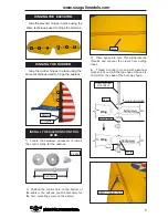
3) Put the stabilizer into place in the
position of the fuselage.
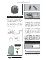
5) When you are satisfied with the align-
ment, hold the stabilizer in place with T- pins
or masking tape, but do not glue at this time.
Pen.
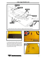
7) Remove the stabilizer. Using the lines
you just drew as a guide, carefully remove the
covering from between them using a model-
ing knife.
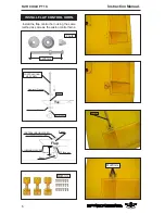
Remove the covering.
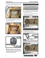
Epoxy.
8) Using a modeling knife, carefully re-
move the covering that overlaps the stabilizer
mounting platform sides in the fuselage. Re-
move the covering from both the top and the
bottom of the platform sides.
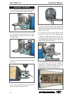
9) When you are sure that everything is
aligned correctly, mix up a generous amount
of 30 Minute Epoxy. Apply a thin layer to the
bottom of the stabilizer mounting area and to
the stabilizer mounting platform sides in the
fuselage. Putting the stabilizer in place and
realign. Double check all of your measure-
ments once more before the epoxy cures.
Hold the stabilizer in place with T-pins or mask-
ing tape and remove any excess epoxy using
a paper towel and rubbing alcohol.
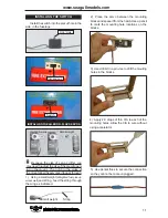
When cutting through the covering to
remove it, cut with only enough pressure
to only cut through the covering itself. Cut-
ting into the balsa structure may weaken
it.


