


Operation and maintenance
25
Operation and maintenance
This section describes important operational procedures for the Viper 200 drive. It
covers the following topics:
•
Front Panel Display
•
Loading and Unloading a Cartridge
•
Drive Maintenance (cleaning the tape drive)
Front panel display
There are several front panels available for the Viper 200. Which panel is delivered
with the drive depends on whether the drive will be used in a automation
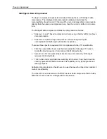
environment, such as a tape library, or as a stand-alone drive. A generalized view of
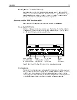
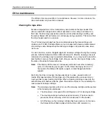
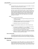
the front-panel display is shown in Figure 9.
Status
LED
(Amber)
Error
LED
(Orange)
Drive
LED
(Green)
Power
LED
(Green)
Tape
Load/Unload
Button
Tape Cartridge Slot
Figure 9. Generic front panel display for Viper 200
All drives have four lights on the front panel. The functions and colors of the lights
are summarized in the following paragraphs.
•
Power LED (green) – The Power light blinks during drive power-up and Power-
on Self Test (POST). If there is an error during the POST, the Power light
remains on (not blinking), along with the Error light, as described below. During
normal operation, the Power light is remains on (not blinking).
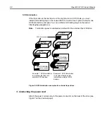
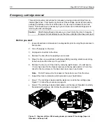
4


