9711-44 Ku-Band TXRX
Installation (168” Radome)
4-43
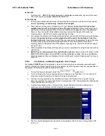
At the ACU:
1.
From the ACU - REMOTE BALANCE parameter: Enable balance mode (refer to your ACU manual).
The screen should now display “REMOTE BALANCE ON”.
At the Antenna:
2.
At the Antenna: Balance the antenna with the elevation near horizon (referred to as front to back
balance)
by adding, or subtracting, small counter-weights
.
3.
Then balance Cross Level axis (referred to as left-right balance)
by moving existing counter-
weights from the left to the right or from the right to the left
. Always move weight from
one location on the equipment frame to the same location on the opposite side of the equipment
frame (ie from the top left of the reflector mounting frame to the top right of the reflector
mounting frame). Do NOT add counter-weight during this step.
4.
Last, balance the antenna with the elevation pointed at, or near, zenith (referred to as top to bottom
balance)
by moving existing counter-weights from the top to the bottom or from the
bottom to the top
. Always move weight from one location on the equipment frame to the same
location on the opposite side of the equipment frame (ie from the top left of the reflector
mounting frame to the bottom left of the reflector mounting frame). Do NOT add counter-weight
during this step.
5.
When completed, the antenna will stay at any position it is pointed in for at least 5 minutes (with no
ship motion).
6.
Do NOT cycle antenna power to re-Initialize the antenna. Return to the ACU, which is still in
REMOTE BALANCE mode, and press ENTER to exit Remote Balance Mode. When you exit Balance
Mode the antenna will be re-initialized, which turns DishScan®, Azimuth, Elevation and Cross-Level
drive ON.
4.15.5.
Fine Balance and Monitoring Motor Drive Torque
The DacRemP
DISPTC
graph chart provides a means for monitoring torque commands required for each
motor for diagnostic purposes and verifying antenna balance. By observing each trace, the required drive of
the antenna via the motor driver PCB may be established.
•
To view the Torque Commands, select the
graph chart.
•
This chart displays the Torque Command errors for each axis via three traces, CL (Cross Level), LV
(Elevation), and AZ (Azimuth), at a fixed 0.195 amps/vertical division.
•
In all axes, tracing centered on the reference line means that that axis drive is neutral. Tracing
above the reference line means that that axis is being driven CCW. Tracing below the reference line
means that that axis is driving CW.
•
A normal trace display will be ± 1 divisions from the red reference line while under calm sea
conditions and with DishScan® Drive turned off, as shown below.
•
The Cross Level displayed above the reference line indicates that the CL axis is being driven CCW
(Left in CL).
Содержание 9711-44 KU-BAND TX/RX
Страница 3: ......
Страница 12: ...Table of Contents xii This Page Intentionally Left Blank ...
Страница 24: ...Site Survey 9711 44 Ku Band TXRX 2 8 This Page Intentionally Left Blank ...
Страница 64: ...Installation 144 Radome 9711 44 Ku Band TXRX 3 40 This Page Intentionally Left Blank ...
Страница 112: ...Basic Setup of the ACU 9711 44 Ku Band TXRX 5 4 This Page Intentionally Left Blank ...
Страница 114: ...Setup Ships Gyro Compass 9711 44 Ku Band TXRX 6 2 This Page Intentionally Left Blank ...
Страница 116: ...Setup Band Select 9711 44 Ku Band TXRX 7 2 This Page Intentionally Left Blank ...
Страница 122: ...Setup Home Flag Offset 9711 44 Ku Band TXRX 9 4 This Page Intentionally Left Blank ...
Страница 130: ...Setup Searching 9711 44 Ku Band TXRX 11 6 This Page Intentionally Left Blank ...
Страница 142: ...Setup Modem Connections Setup and Test 9711 44 Ku Band TXRX 13 8 This Page Intentionally Left Blank ...
Страница 150: ...Antenna Specific Operation 9711 44 Ku Band TXRX 16 4 This Page Intentionally Left Blank ...
Страница 154: ...Functional Testing 9711 44 Ku Band TXRX 17 4 This Page Intentionally Left Blank ...
Страница 158: ...Installation Troubleshooting 9711 44 Ku Band TXRX 18 4 This Page Intentionally Left Blank ...
Страница 180: ...Maintenance 9711 44 Ku Band TXRX 19 22 This Page Intentionally Left Blank ...
Страница 198: ...Drawings 9711 44 Ku Band TXRX 23 2 This Page Intentionally Left Blank ...
Страница 205: ......
Страница 208: ...D C B A A B C D 1 2 3 4 5 6 7 8 8 7 6 5 4 3 2 1 SIZE SCALE SHEET NUMBER DRAWING NUMBER REV B 1 15 140165 B 2 OF 3 ...
Страница 209: ...D C B A A B C D 1 2 3 4 5 6 7 8 8 7 6 5 4 3 2 1 SIZE SCALE SHEET NUMBER DRAWING NUMBER REV B 1 15 140165 B 3 OF 3 ...
Страница 210: ......
Страница 218: ......
Страница 230: ......
Страница 231: ......
Страница 242: ......
Страница 243: ......
Страница 252: ......
Страница 254: ......
Страница 256: ......


