248 BAY SERIES
17
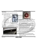
Helm Station:
The Helm Station is located in the Cockpit of the Vessel,
and is the area equipped with the tools and features that
allow operation of the vessel.
•
Battery Selector Switch
•
Engine Shutdown Safety
Switch
•
Engine Controls
•
Steering Controls
•
Helm Switch Panel
•
Instrumentation &
Navigation
(*Optional Equipment)
•
Audio / Stereo
(*Optional Equipment)
•
Compass
*See Owner
’
s Manuals for Optional Equipment Installed
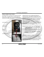
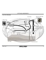
Battery Selector Switch Compartment & Switch:
Located at the lower part of the Helm is a compartment
which contains the Battery Selector Switch.
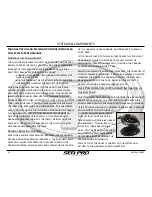
This switch allows the operator to provide power to and
disconnect power from the operating systems.
There are four (4) switch positions (OFF, 1, 2, 1 +2) that
provide the following functions:
OFF: In this position, power is disconnected from all
systems, and should be used when the vessel is being
stored or not in use. This prevents any unnecessary
power drain from the batteries should an operating
system be accidentally left on.
1 or 2: In these positions, all power and current is
supplied from either the Starboard (1) or Port (2) battery,
and the charging current from the engine will be
directed to the selected battery. The opposite battery is
now completely isolated, and does not provide any
current to the operating systems nor does it receive any
charging current from the engine.
1+2: In this position, both of the batteries are now
connected in parallel, with both providing power and
current to the operating systems and receiving charging
current from the engine.
SYSTEMS & COMPONENTS
Содержание 248
Страница 1: ...Owner s Manual and Quick Reference Guide 2017 WWW SEAPROMFG COM 248BAYSERIES ...
Страница 39: ...248 BAY SERIES 39 SCHEMATICS WIRING DIAGRAMS 248 Bay Deck Wiring Harness Diagram ...
Страница 40: ...40 248 BAY SERIES SCHEMATICS WIRING DIAGRAMS 248 Bay Hull Wiring Harness Diagram ...
Страница 41: ...248 BAY SERIES 41 SCHEMATICS WIRING DIAGRAMS 248 Bay Battery Wiring Harness Diagram ...
Страница 42: ...42 248 BAY SERIES SCHEMATICS WIRING DIAGRAMS 248 Bay Amp Power Wiring Diagram ...
Страница 43: ...248 BAY SERIES 43 SCHEMATICS WIRING DIAGRAMS 248 Bay Dash Helm Switch Panel Diagram ...
Страница 44: ...44 248 BAY SERIES SCHEMATICS WIRING DIAGRAMS 248 Bay Inside Helm Console Wiring Diagram ...
Страница 45: ...248 BAY SERIES 45 SCHEMATICS WIRING DIAGRAMS 248 Bay Trolling Motor Trim Control Panel Wiring Diagram ...
Страница 46: ...46 248 BAY SERIES SCHEMATICS WIRING DIAGRAMS 248 Bay Hard Top Optional Switch Panel Diagram ...
Страница 47: ...248 BAY SERIES 47 SCHEMATICS WIRING DIAGRAMS 248 Bay Hard Top Optional Wiring Harness Diagram ...

