background image

3

IN

 AU

STRAL

IA

PR

OU

DLY BUILT

6. PC OR MAC CONNECT SOFTWARE

• 

As the module is DHCP default, this software will allow simple operation and identification 
of IP address and port number of IP connect modules on network

• 

PC Connect software will search for Connect IP Modules on the network

• 

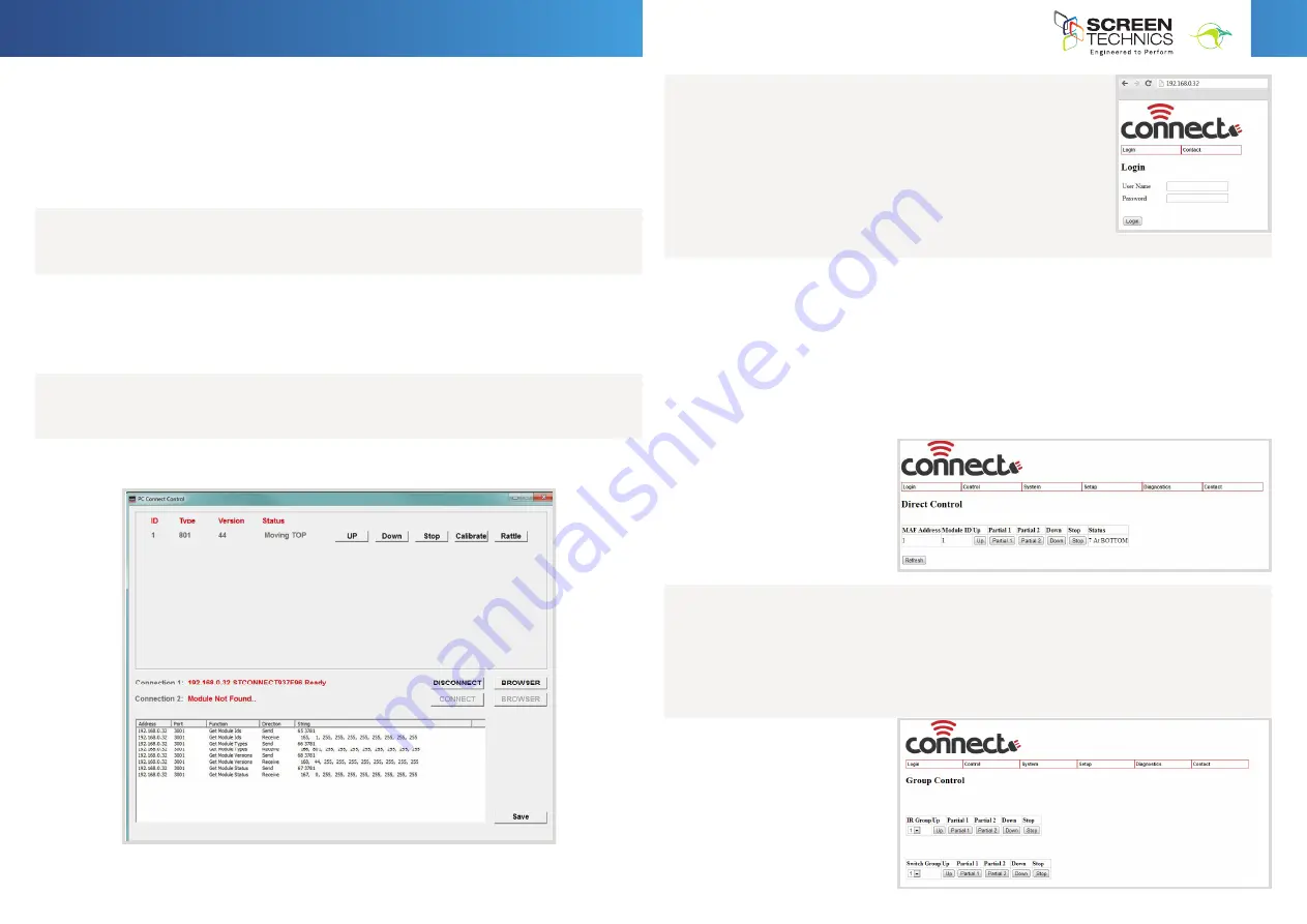
Screen shot below showing module, IP address using PC Connect

• 

Connect to module

The PC Connect software is found on our web site:

screentechnics.com.au

 and can be accessed through the FAQ menu.

• 

Screen shot below of module connected

• 

Allows operation of module via simple control

• 

When command is sent – string showing command, IP address, Port number and feedback 
response is shown in the box below

• 

Click on Web Page button and via a web browser you are now connected to the actual 
Connect module directly. This page also has basic control.


h.


Click on Browser button and simple control screen 

appears  


i.


Click on login to view advanced settings page  


7.


Connect Internal Web Browser  

a.


Using web browser 


b.


Type IP address as shown in PC Connect Software


c.


Connect Login screen will be shown  


d.


Input  User Name : 

Admin


e.


Password : 

Connect 


Continued Over.../

INSTRUCTIONS - 

MASTERFIT IP 

A, A+, B, B+, C, C+ Projection Screen

7. ALTERNATE CONNECTION VIA WEB BROWSER

• 

Connect to the module using the IP address via a web browser.

• 

Type IP address as shown in PC Connect software into the 
browser.

• 

Connect to the basic control and advanced login screen.

• 

Default Input User Name : Admin

• 

Password : Connect

• 

Both the User Name and Password are changeable in software if 
required.

8. DIRECT CONTROL

• 

Login will default take you to this page.

• 

Direct Control Screen shown below.

• 

Note that Partial 1 & 2 buttons on this page act as stop commands unless the partials have 
been set in programming.

• 

The MAF address (physical location in Connect network of up to 9) and Module ID (same as 
MAF unless changed in programing) is shown.

• 

Simple control operation for test set-up.

• 

Status indication of screen – use refresh to obtain latest status update.

9. GROUP CONTROL

• 

Select the Control tab and use dropdown box to choose Group Control.

• 

Control Screens that have been programmed with the same IR group or switch group 
(contact Close input)

• 

Partial 1 & 2 act as stop command unless partial has been programmed

• 

Simple control feature


8.


Connect Internal Web Browser  

a.


Select Direct Control from Control Menu 

b.


Direct Control Screen shown below  

c.


Partial 1 & 2 act as stop command unless partial has been programmed  

d.


MAF address and Module ID shown  

e.


Simple control feature  

f.


Status indication of screen – use refresh to obtain latest status update  


9.


Group Control 


a.


Direct Control Screens that have been programmed with the same IR group or switch group 
(contact Close input) 

b.


Partial 1 & 2 act as stop command unless partial has been programmed  

c.


Simple control feature  


h.


Click on Browser button and simple control screen 

appears  


i.


Click on login to view advanced settings page  


7.


Connect Internal Web Browser  

a.


Using web browser 


b.


Type IP address as shown in PC Connect Software


c.


Connect Login screen will be shown  


d.


Input  User Name : 

Admin


e.


Password : 

Connect 


Содержание MASTERFIT IP

Страница 1: ...ntact input Requires momentary contact only Contact is closed and opened between Up Common screen moves to up limit Contact is closed and opened between Down Common screen moves to bottom limit Stop command is sent when both Up Down contact closed together 2 Infra Red Receiver Packaged with 300mm and 1 2 M lead from motor board to IR receiver Packaged with standard 2 channel IR transmitter Screen ...

Страница 2: ...witch Clockwise always increases the amount of rotation travel of the motor Anti clockwise always reduces the amount of rotation travel of the motor So pick the switch responsible for the limit position up or down Clockwise turning of the switch will always let the motor travel further in that direction Anti clockwise turning of the switch will lessen the amount of travel in that direction Can I a...

Страница 3: ...ion in Connect network of up to 9 and Module ID same as MAF unless changed in programing is shown Simple control operation for test set up Status indication of screen use refresh to obtain latest status update 9 GROUP CONTROL Select the Control tab and use dropdown box to choose Group Control Control Screens that have been programmed with the same IR group or switch group contact Close input Parti...

Страница 4: ... IP operating parameters e AMX Discoverable enable f Screen Technics Beacon g Simple control page Continued Over INSTRUCTIONS MASTERFIT IP A A B B C C Projection Screen 11 REGISTER SETTINGS Access this menu by selecting System then Module Settings Select MAF address or Module ID and select load Change value and select update This menu will enable changes of features within the module 127 registers...

Страница 5: ...ister 74 to a value of 2 If you wish the module to operate on Group 1 2 only change register 74 to a value of 6 SWITCH GROUP BITMAP REGISTER Calculate the register number by using the table Transfer the value for each required group to the right column The total of the values in the right column then becomes the Register Value E g to set groups 1 2 4 then the Total value is 22 Group Value 1 2 2 4 ...

Страница 6: ...NDS IR group control can be used to control screens directly if connected via Connect Network including the Connect IP module Each module will require programming via register 75 as per point 11 in document Example of direct command Connected to 192 168 0 32 3001 command 20 1 would see all screens programmed to operate on IR group 1 move to up position Command followed by value 0 operates all modu...

Страница 7: ... 2 VALUE 3 150 Status Module ID Module Status Register 0x20 Response from module e g 150 1 1 6 value 6 indicates screen at top Note Status 1 is returned if valid data and no further records in the status buffer Status 2 is returned if valid data and there are still records in status buffer Status 3 is returned if valid data but the buffer is full eg may have lost data Status 6 is returned if there...

Страница 8: ...ction is exited when screen operation finished or another screen operate command is acted on Double short press for 2 seconds approximately per button press Screen Up command Screen travels to up limit LED single flashes while in this function Pressing button again stops screen Function is exited when screen travels to up position or another screen operate command is sent Triple short press for 2 ...

Отзывы: