KeyPad service manual
Rev.1.1
47
11. INDEX
Figure 1 : Symptoms vs. document references ...................................... 8
Figure 2 :
Digi
PREP
KeyPad controller physical diagram ..................... 10
Figure 3 : KeyPad layout ...................................................................... 11
Figure 4 : KeyPad displsy mounting view ............................................. 14
Figure 5 : General KeyPad block diagram ............................................ 16
Figure 6 : LED cable position ................................................................ 17
Figure 7 : Backlight and R4 location ..................................................... 18
Figure 8 : LCD display ribbon cable position ........................................ 19
Figure 9 : KeyPad electronic diagram ................................................... 20
Figure 10 : KeyPad resistors location ................................................... 22
Figure 11 : Push button measuring location ......................................... 23
Figure 12 : AC/DC converter ................................................................ 24
Figure 13 : Power connections ............................................................. 25
Figure 14 : Diodes and regulator location ............................................. 26
Figure 15 : Monostable and solid state relay circuit .............................. 27
Figure 16 :
Digi
SET
connector location ................................................ 28
Figure 17 : Heating system LED indicator location ............................... 29
Figure 18 : Monostable pin location (U3) .............................................. 30
Figure 19 : SSR test pins location......................................................... 31
Figure 20 : SSR output when heating section is firing .......................... 32
Figure 21 : JP2 connector location ....................................................... 33
Figure 22 : A/D, oscillator and regulator location .................................. 34
Figure 23 : CPU daughter card location ................................................ 35
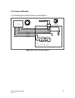
Figure 24 : Heater general diagram ...................................................... 41
Figure 25: Heating Block internal connection ……………………………42
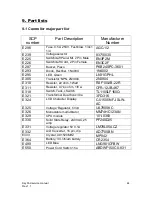
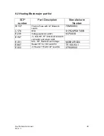
Figure 26 : Heating Block Parts ............................................................ 43
Figure 27 : Heating pad resistance ....................................................... 43
Содержание DigiPREP HP
Страница 48: ...KeyPad service manual Rev 1 1 48 ...
Страница 49: ...KeyPad service manual Rev 1 1 49 ...


