background image

Technical data 


24 

01.00|ROTA THW vario |en-US 


  •  max. RPM n

max

 = 3200 RPM ("Lathe chuck data" table)  

  •  RPM n = 1200 min

-1

 (application-specific) 

  •  Mass of one (!) top jaw m

AB

 = 5.33 kg (application- 

specific) 

  •  Center of gravity radius of top jaw r

sAB

 = 0.107 m (application-

specific) 

  •  Safety factor S

z

 = 1.5 (according to VDI 3106) 

  •  Safety factor S

sp

 = 1.5 (according to VDI 3106) 

Note:

 Masses of the jaw mounting screws and T-nuts are not taken 

into account. 

 
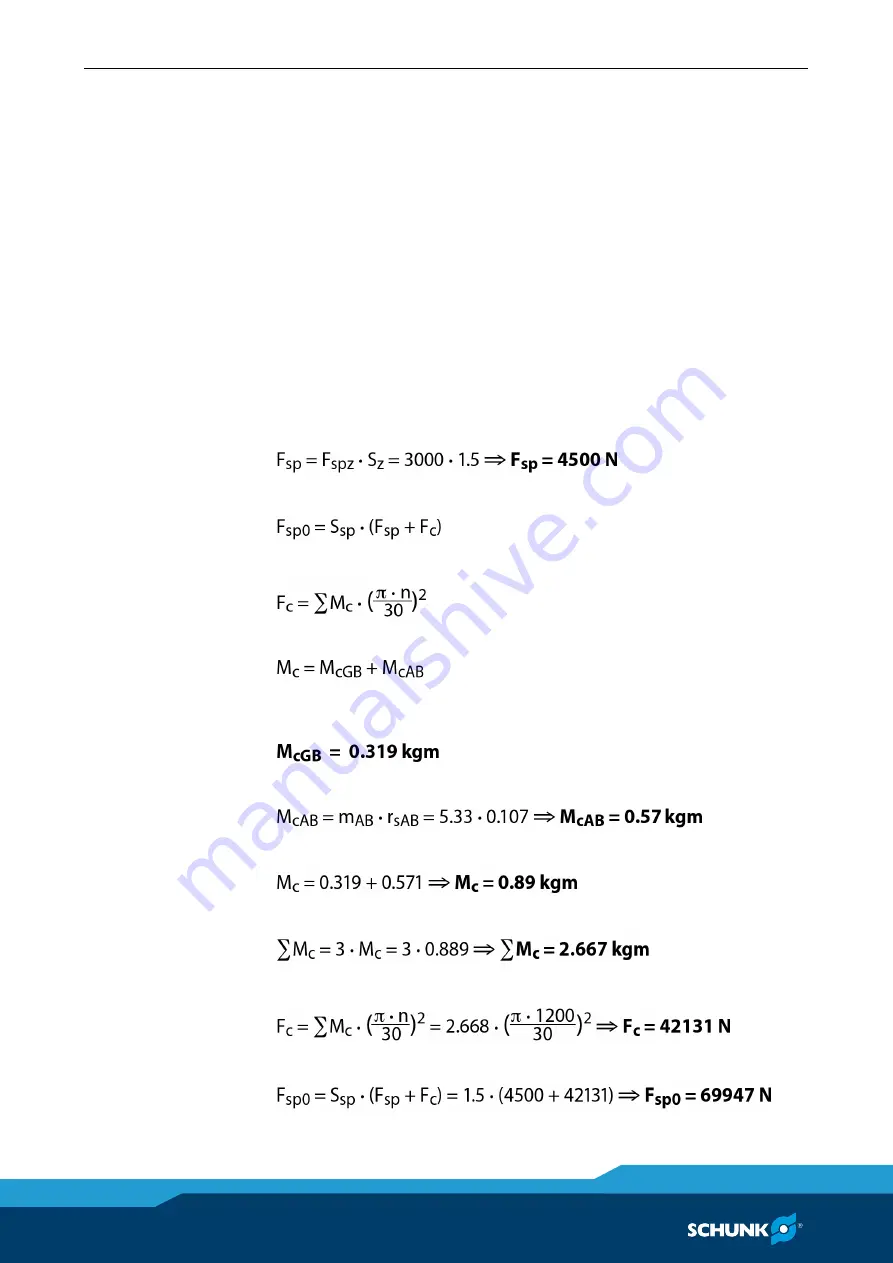
First the required effective clamping force F

sp

 is calculated using 

the machining force stated: 


Initial clamping force during shutdown: 


Calculation of total centrifugal force: 


For two-part chuck jaws, the following applies: 


Take the centrifugal torque of the base jaw and top jaw specified 

from the "Lathe chuck data" table:  


For the centrifugal torque of the top jaw, the following applies: 


Centrifugal torque for one jaw: 


The chuck has 3 jaws, the total centrifugal torque is: 


The total centrifugal force can now be calculated: 


Initial clamping force during shutdown that was sought: 


Содержание ROTA THWvario

Страница 1: ...Translation of Original Operating Manual Jaw quick change with arbor or collet chuck adapter ROTA THW vario Assembly and Operating Manual Superior Clamping and Gripping ...

Страница 2: ...pany the leading technology supplier of robots and production machines Our team is always available to answer any questions on this product and other solutions We look forward to your challenging questions We will find a solution Best regards Your SCHUNK team H D SCHUNK GmbH Co Spanntechnik KG Lothringer Str 23 D 88512 Mengen Tel 49 7572 7614 0 Fax 49 7572 7614 1099 info de schunk com schunk com C...

Страница 3: ...rques 18 6 Technical data 19 6 1 Chuck data 19 6 2 Clamping force RPM diagrams 20 6 3 Calculating the clamping force and RPM 21 6 3 1 Calculation of the required clamping force at a specified speed of rotation 21 6 3 2 Calculation example required initial clamping force for a given RPM 23 6 3 3 Calculation of the permissible RPM in case of a given initial clamping force 25 6 4 Accuracy classes 26 ...

Страница 4: ...e chuck 47 10 Troubleshooting 49 10 1 Segmented mandrel ROTA THW vario D 49 10 2 Collet chuck ROTA THW vario F 50 11 Maintenance 51 11 1 General information 51 11 2 Cleaning 52 11 3 Lubrication 52 11 4 Maintenance plan 53 11 5 Technical condition 55 11 6 Changing the stepped jaws 55 12 Spare parts 56 12 1 ROTA THW vario 215 62 56 12 1 1 Versions and spare parts segmented mandrel ROTA THW vario D 5...

Страница 5: ...01 00 ROTA THW vario en US 5 14 2 Collet chuck ROTA THW vario F 70 14 2 1 HSW clamping heads for self turning 70 14 2 2 Changing device 73 14 2 3 Jaw turning rings 75 15 Declaration of Incorporation 77 ...

Страница 6: ...sure to include this operating manual The illustrations in this operating manual are intended to provide a basic understanding of the product and may deviate from the actual version We accept no liability for damage resulting from failure to observe and comply with this operating manual Safety notes To make risks clear the following signal words and symbols are used for safety notes DANGER Danger ...

Страница 7: ...arning about hand injuries WARNING Warning about hot surfaces Applicable documents General terms and conditions Catalog data sheet for purchased product Calculation of the jaw centrifugal forces in the chapter Technology of the lathe chuck catalog The documents indicated with an asterisk can be downloaded from schunk com 1 2 ...

Страница 8: ...manual accessible to all users at all times If transferring the product to a third party be sure to include this manual Appropriate use This product is intended for clamping workpieces on lathes and other suitable machine tools The product may only be used within the scope of its technical data 6 Page 19 The product is intended for industrial and industry oriented use Appropriate use of the produc...

Страница 9: ...ons and property if for example it is not used as intended it is not installed or maintained properly the safety and installation instructions local applicable safety and accident prevention regulations or the EC Machinery Directive are not observed DANGER Possible risk of fatal injury to operating personnel if a jaw breaks or if the chuck fails because the technical data have been exceeded and a ...

Страница 10: ...king on the machine and the lathe chuck WARNING Risk of injury due to dropping the chuck during transport installation or removal Take special care in the danger zone when transporting installing or removing the lathe chuck Note the relevant load securing regulations for working safely with cranes ground conveyors lifting gear and load handling equipment CAUTION Risk of slipping or falling if the ...

Страница 11: ...atures Wear protective gloves when removing the workpieces Automatic loading is preferred CAUTION Risk of damage due to incorrect choice of clamping position for chuck jaws on workpiece If an incorrect clamping position is chosen for the chuck jaws on workpiece the base and top jaws may break Make sure that the workpiece is clamped concentrically If the chuck has a quick change jaw system the top ...

Страница 12: ...semble the chuck and remove excess grease For lubrication refer to the chapter Maintenance Notes on safe operation Do not start the machine spindle until the workpiece is clamped and the spanner wrench has been removed from the clamping device Functional test After installation of the clamping device its function must be checked prior to commissioning Clamping force The max clamping force specifie...

Страница 13: ...eral times lubricate again and then check the clamping force We recommend checking the clamping force using a clamping force tester e g GFT 270 ID 0890013 before starting a new production run and between maintenance intervals Optimum safety can only be guaranteed through regular checks The clamping force should always be measured in the state of the chuck as used for the current clamping situation...

Страница 14: ... rules The chuck jaws should be designed to be as light and as low as possible The clamping point must be as close as possible to the chuck front Clamping points at a greater distance cause higher surface pressure in the jaw guidance and can significantly reduce the clamping force Do not use welded jaws If for constructional reasons the special chuck jaws are wider and or higher than the top jaws ...

Страница 15: ...d be take advantage of the manufacturer s training courses Every person called upon by the operator to work on the clamping device must have read and understood the complete assembly and operating manual especially Chapter 2 Basic safety notes 2 Page 8 The responsibility for operation maintenance and repair must be clearly specified Only allow personnel who are considered experts in the context of...

Страница 16: ...haracteristics the machine where the manual lathe chuck is mounted must be immediately stopped and remain shut down until the fault has been located and remedied Only allow specialists to remedy malfunctions Spare parts Only use original SCHUNK spare parts Environmental regulations The applicable environmental regulations must be observed for all maintenance and repair work The use of petroleum et...

Страница 17: ...mbient conditions and operating conditions Observe the maximum number of clamping cycles approx 500 000 cycles Observance of the specified maintenance and lubrication intervals 10 Page 49 Parts touching the workpiece and wearing parts are not part of the warranty Scope of delivery ROTA THW vario 215 62 1 Flange 1 Bayonet adapter 1 Set of protective jaws Screws ROTA THW vario D Segmented mandrel Sc...

Страница 18: ...uck screw quality 10 9 Screw size M6 M8 M10 M12 M14 M16 M18 M20 M22 M24 M27 M30 Tightening torques MA Nm 13 28 50 88 120 160 200 290 400 500 1050 1500 Tightening torques for mounting top jaws onto the lathe chuck screw quality 12 9 Screw size M8 M10 M12 M16 M20 M24 Maximum admissible torque Nm 25 60 80 100 180 230 5 ...

Страница 19: ...rdened standard stepped jaws that go with the chuck If unhardened top jaws or special chuck jaws are used ensure that the weight is as low as possible For soft top jaws or special chuck jaws the speed of rotation permitted for the cutting task must be calculated in accordance with VDI 3106 whereby the maximum recommended speed may not be exceeded The calculated values must be checked by dynamic me...

Страница 20: ...set flush with the outer diameter of the chuck The chuck is in perfect condition and lubricated with SCHUNK LINOMAX special grease If one or more of these prerequisites is modified the graphs will no longer be valid Chuck setup for clamping force RPM diagram FspB Jaw clamping force S Center of gravity rs Center of gravity radius amax Max jaw eccentricity of center of gravity in axial direction Fma...

Страница 21: ... set kg sz Safety factor for machining Mc Centrifugal torque kgm Σs Max clamping force of lathe chuck N kgm 9 81 Nm Calculation of the required clamping force at a specified speed of rotation The initial clamping force Fsp0 is the total force impacting radially on the workpiece via the jaws due to actuation of the lathe chuck during shutdown Under the influence of rotation the jaw mass generates a...

Страница 22: ...workpiece is released spontaneously Do not exceed the calculated RPM Do not fall below the necessary minimum clamping force Reduction in effective clamping force by the magnitude of the total centrifugal force for gripping from the outside inwards The required effective clamping force for machining Fsp is calculated from the product of the machining force FspZ and the safety factor Sz This factor ...

Страница 23: ...mping force The formula for the calculation of the total centrifugal force Fc is For this n is the given speed of rotation in RPM The product mB rs is referred to as the centrifugal torque Mc In case of toolholders with split chuck jaws i e with base jaws and top jaws for which the base jaws change their radial position only by the stroke amount the centrifugal torque of the base jaws McGB and the...

Страница 24: ... not taken into account First the required effective clamping force Fsp is calculated using the machining force stated Initial clamping force during shutdown Calculation of total centrifugal force For two part chuck jaws the following applies Take the centrifugal torque of the base jaw and top jaw specified from the Lathe chuck data table For the centrifugal torque of the top jaw the following app...

Страница 25: ...n Permissible RPM for a given effective clamping force The following data is known from previous calculations Initial clamping force during shutdown Fsp0 17723 N Machining force for machining job Fspz 3000 N application specific Total centrifugal torque of all jaws Mc 2 668 kgm Safety factor Sz 1 5 according to VDI 3106 Safety factor Ssp 1 5 according to VDI 3106 NOTE Masses of the jaw mounting sc...

Страница 26: ... class 6 3 according to DIN ISO 21940 11 Residual imbalance risks may arise due to insufficient rotation compensation being achieved see DIN EN 1550 6 2 e This applies in particular to high speeds of rotation asymmetrical workpieces or the use of lathe chucks that do not correspond to balancing grade 6 3 as well as uneven lubricant application In order to prevent damage resulting from these residu...

Страница 27: ... tools The vario D is a segmented mandrel that may only be used in a ROTA THW vario 215 62 The vario D is screwed onto the face of the power chuck and operated hydraulically via a special adapter The protective jaws item 82 move in the power chuck 8 2 1 Page 33 Simultaneous workpiece clamping with the power chuck and the segmented mandrel is not possible as no independent clamping force applicatio...

Страница 28: ...ned steel segments vulcanized together These are characterized by parallel workpiece clamping high accuracy with minimum deformation of the workpieces and fast set up When using the vario F as a stop chuck a workpiece stop is screwed into the chuck Due to the axial tensile forces during clamping the workpiece is firmly pulled onto the flexible stop This results in a very stable clamping of the wor...

Страница 29: ...liding sleeve for clamping and unclamping If an intermediate position can be programmed at the stroke control in the clamping cylinder it would be possible to move with optimized actuation paths using a special attachment to the vario F The attachment of the power chuck remains unaffected Important The actuating pressure must be adapted for the power chuck and for the collet chuck when re equippin...

Страница 30: ...e with DIN 6386 and ISO 3089 The contact surface must be chamfered and clean at the bore holes Attaching the THW vario chuck Remove the chuck from its packaging and check for damage completeness Move the draw tube to its foremost position by actuating the clamping cylinder see Image 6 1 NOTE It is important to make sure that the piston can be moved to the foremost jaw change position To do this en...

Страница 31: ... 3 Screw the chuck with the piston thread onto the adapter 4 Only tighten the lathe chuck slightly on the flange with the supplied screws as the lathe chuck must be aligned 5 Move base jaws in the chuck to the maximum position 6 Remove center sleeve item 4 To do this remove the screws item 43 and screw them into the adjacent threads to press the center sleeve off 7 Align the lathe chuck according ...

Страница 32: ...e the cylinder into the front position Unlock the wedge bars with the jaw change key supplied and slide or offset the base jaws into the chuck s jaw guidance as shown on markings 1 2 and 3 Check that the base jaw and jaw stroke can easily move The parts are disassembled in the same way but in the reverse order ...

Страница 33: ...the segmented clamping sleeve stop etc still need to be fitted The segmented mandrel vario D is only prepared for use on a ROTA THW vario 215 62 Any other application must be discussed with SCHUNK The attachment between power chuck and lathe must be prepared for the use by the vario D A suitable bayonet adapter with the corresponding flange must be used between the power chuck and the machine 8 2 ...

Страница 34: ...d screw them into the adjacent threads to press the center sleeve off 3 Clean the taper the flat surfaces and the bayonet before assembly 4 Insert the vario component into the lathe chuck so that the marking on the circumference of the vario is aligned with the base jaw guide The bayonets can be slid into each other in this position 5 Tighten vario with 3 screws item 48 on the chuck face screws DI...

Страница 35: ...tamination To check the accuracy the clamping bolt and the segmented clamping sleeve must be removed Unscrew and remove the clamping bolt with a hexagon socket wrench Pull down the segmented clamping sleeve Remove the workpiece stop by removing the screws For the axial run out place the dial gauge on the axial stop face of the stop For the concentricity place the dial gauge on the outer taper of t...

Страница 36: ...ve care must be taken to ensure that the drivers engage in the segmented clamping sleeve Use the hexagon socket wrench to screw the clamping bolt back in until it reaches the block The following torque must be observed here Mandrel size Clamping bolt thread Recommended tightening torque 0 M7 x 1 10 Nm 1 M9 x 1 20 Nm 2 M14 x 1 25 Nm 3 M25 x 1 55 Nm Changing the stops The stops are changed by loosen...

Страница 37: ...2 the idle stroke bolt item 6 and the bayonet piece item 7 can be removed By loosening the radial fixing pin item 11 the actuating cone item 5 can be removed from the mandrel body item 1 The bolt item 15 and ejector pins item 4 can be removed from the mandrel body item 1 Clean the individual components and check all parts for damage and wear Only use original SCHUNK spare parts when replacing dama...

Страница 38: ... mandrel on the power chuck The collet chuck is delivered ready for assembly Only accessories such as the clamping heads stop etc still need to be fitted The collet chuck vario F is only prepared for use on a ROTA THW vario 215 62 Any other application must be discussed with SCHUNK 8 3 8 3 1 ...

Страница 39: ...tem of the chuck is opened when the center sleeve or the vario component are changed No chips may penetrate into the mechanical system of the chuck 2 Remove center sleeve item 4 To do this remove the screws item 43 and screw them into the adjacent threads to press the center sleeve off 3 Clean the taper the flat surface and the bayonet before assembly 4 Insert the vario component into the lathe ch...

Страница 40: ...e power chuck Here the influence of wear marks and damage is a factor as well as contamination To check the accuracy the clamping head must be removed It may be necessary to align the clamping device holder To do this place a dial gauge in the taper and turn the spindle If the concentricity error is greater than 0 01 mm the clamping taper can be aligned With the spindle stationary loosen the 6 M10...

Страница 41: ...pressed in the coupling area Insert the clamping head into the chuck body with the fixing bolts item 6 engaging in the milled fixing grooves item 17 in the segment centers never in the vulcanized slots Use slight pressure to loosen and pull out the changing device in the spindle direction WARNING When operating the changing device do not reach into the moving parts due to the risk of crushing Remo...

Страница 42: ...this washer M12 for vario F 65 and vario F 80 and M20 x 1 5 for vario F100 Additionally the stop washer can be unscrewed and reworked When reworking care must be taken to ensure that the interior is not penetrated The openings can cause the collet chuck to become dirty and thus impair its function If no axial stop is required the bore should be closed with a locking screw 8 3 3 ...

Страница 43: ...n be removed Remove screws item 11 and remove the chuck body item 1 from the mount item 2 Expand the fixing taper and pull it down over the mount item 2 The lathe chuck is disassembled in the same way but in the reverse order After cleaning and oiling we recommend storage in a closed box Clean the individual components and check all parts for damage and wear Only use original SCHUNK spare parts wh...

Страница 44: ... base jaws are unlocked mechanically For each jaw guidance a jaw change bolt with hexagon socket which can be turned using the chuck key is arranged on the chuck perimeter Turning the jaw change bolt moves the serration for the wedge bar against spring pressure to the rear and out of the serration for the base jaw In this position the base jaws can be changed or moved radially inwards or outwards ...

Страница 45: ...he lathe chuck under clamping pressure When turning or grinding the jaw turning ring or turning pin must be clamped by the top jaws and not by the base jaws Keep the base jaws and top jaws screwed in place for recurring work Tighten the jaw mounting screws to the specified torque WARNING Tighten the jaw mounting screws with a torque wrench Never tighten the Allen key with an extension pipe or by h...

Страница 46: ...mechanical system of the chuck If top jaws should be used which are wider than 22 mm the center sleeve with narrow cover plates must be used The plates are nondetachable and fixed to the center sleeve They must not be unscrewed for safety reasons Identification number for complete center sleeve Center sleeve design For a top jaw width up to 22 mm For a top jaw width over 22 mm Standard with throug...

Страница 47: ...crews and take off the mount Remove the safety bolt item 14 with compression spring item 35 and spring bolt item 13 Use a suitable tool to push out and remove the jaw change bolt item 8 with the balls item 37 through the bore hole for the safety bolt Check the seal item 33 for damage and wear and replace it if necessary Pull the piston item 3 together with the wedge bar set item 9 out of the chuck...

Страница 48: ...side of the wedge bar item 9 approx 6 mm The pressure bolt item 12 then becomes visible The displacement force is reduced through slight pressure on the serration Secure the pressure bolt item 12 against flying off and then completely remove the eccentric bolt item 10 out of the wedge bar item 9 Take the angle with plunger pin item 15 and pressure piece item 16 with compression spring item 34 off ...

Страница 49: ...ing bolt and segmented clamping sleeve Remove and clean clamping bolt and segmented clamping sleeve Error in shape of the workpiece Shaped starting material has been elastically deformed during clamping After machining the workpiece relaxes and returns to its original shape Use of starting material with a reduced shape error Impressions on the clamping face Pointed or linear workpiece clamping Dim...

Страница 50: ... Remove the clamping head retract the clamping tube and clean the gap in the coupling area Check the design of the draw tube thread adapter 10 or the pull mechanism 4 and correct if necessary Error in shape of the workpiece Starting material with a shape error has been elastically deformed during clamping After machining the workpiece relaxes and returns to its original shape Use of starting mater...

Страница 51: ... the scope of these maintenance intervals a regular check of the maintenance condition of the clamping device by means of static clamping force measuring devices is absolutely necessary WARNING Risk of injury due to stored energy The clamping device can be designed with springs These springs are under permanent tension The release of the stored energy can lead to injuries The screws secured with s...

Страница 52: ...int free cloth Clean all components with detergent and cloth to remove all oil and grease residues Lubrication WARNING To maintain the safe function of the lathe chuck it has to be regularly lubricated Move the lathe chuck into the open position Lubricate the chuck at the three lubrication nipples Fig 9 1 Arrow using a high pressure grease gun with six strokes of SCHUNK LINOMAX special grease at e...

Страница 53: ...ear and tear Contact SCHUNK if you have any questions about maintenance work and intervals Cleaning interval Maintenance work daily Visual inspection and complete cleaning in case of heavy dirt 11 2 Page 52 weekly Cleaning adaptation clamping device 11 2 Page 52 Lubrication interval Demands every 20 hours normal use of coolant 11 3 Page 52 every 8 hours high use of coolant 11 3 Page 52 1000 1500 h...

Страница 54: ... and stop surfaces must also be carried out to detect damage to the clamping device and the rubber of the clamping element at an early stage The seals in the segmented clamping sleeve must be checked for damage during the maintenance and cleaning intervals and replaced if necessary Only use original SCHUNK spare parts Depending on the amount of dirt a complete cleaning of all moving parts should b...

Страница 55: ...itute for measuring the clamping force If the clamping force has dropped too far or if the base jaws and clamping piston no longer move properly the chuck has to be disassembled cleaned and relubricated NOTE Only use original SCHUNK spare parts when replacing damaged parts Changing the stepped jaws When changing the base or stepped jaws the serration has to be cleaned and greased with SCHUNK LINOM...

Страница 56: ...w change bolt 3 9 Complete wedge bar 3 10 Eccentric bolt 3 11 Pin 3 12 Pressure bolt 3 13 Spring bolt 3 14 Safety bolt 3 15 Plunger pin 3 16 Pressure piece 6 31 Rod seal kit 1 32 O ring DIN 3771 NBR 70 76 00 x 2 00 mm 1 33 O ring DIN 3771 NBR 70 20 00 x 2 00 mm 3 34 Compression spring for pressure piece 3 35 Compression spring for safety bolt 3 36 Compression spring for pressure bolt 3 37 Steel ba...

Страница 57: ...TA THW vario en US 57 Item Designation Quantity 45 Pan head screw 6 48 Screws DIN EN ISO 4762 10 9 6 82 Vario protective jaw 1 83 Adapter for bayonet 1 84 Standard center sleeve 1 88 Flange 1 89 Cover 1 90 Jaw change key 1 ...

Страница 58: ...ke 800 703 800 702 Vario D 2 with idle stroke without idle stroke 800 705 800 704 Vario D 3 with idle stroke without idle stroke 800 707 800 706 Item Designation Quantity 1 Mandrel body 1 2 Clamping bolt 1 3 Ejector ring 1 4 Ejector pins 3 5 Actuating cone 1 6 Idle stroke bolt 1 7 Bayonet piece 1 9 Fixation cone 1 10 Mounting screws 1 11 Radial fixing pin 1 12 Mounting screws 6 13 Seal 1 14 Seal 1...

Страница 59: ... F 65 51 with idle stroke 800 716 Vario F 80 with idle stroke without idle stroke 800 713 800 712 Vario F 100 with idle stroke without idle stroke 800 715 800 714 Item Designation Quantity 1 Chuck body 1 2 Mount 1 3 Pull mechanism 1 5 Base stop 1 6 Idle stroke bolt 1 7 Bayonet piece 1 9 Fixation cone 1 10 Mounting screws 3 11 Mounting screws 6 12 Mounting screws 6 13 Seal 1 14 Seal 1 12 1 2 ...

Страница 60: ...Assembly drawing 60 01 00 ROTA THW vario en US Assembly drawing ROTA THW vario 215 62 13 13 1 ...

Страница 61: ...Assembly drawing 01 00 ROTA THW vario en US 61 ...

Страница 62: ...Assembly drawing 62 01 00 ROTA THW vario en US Segmented mandrel ROTA THW vario D 13 1 1 ...

Страница 63: ...Assembly drawing 01 00 ROTA THW vario en US 63 Collet chuck ROTA THW vario F 13 1 2 ...

Страница 64: ...and clamping it The turning ring must be placed straight onto the segmented clamping sleeve The segmented clamping sleeve can now be turned to the required dimension NOTE Be careful when turning the SAD segmented clamping sleeve The diameter of the SAD sleeve may be turned to the rubber at most but the rubber itself must not be machined For safety reasons the SAD segmented clamping sleeve may only...

Страница 65: ...Recommended tensile forces for the use of turning rings with SAD sleeves ROTA S vario Max actuation moment 200 52 200 62 M0 15 Nm 15 Nm M1 15 Nm 15 Nm M2 30 Nm 30 Nm M3 45 Nm The data on max speed of rotation refer exclusively to the use of segmented clamping sleeves in standard design ...

Страница 66: ...100RØD ABR Ø Size 1 Clamping area Ø 26 mm Ø 38 mm max speed of rotation 4800 RPM max axial tensile force 10 kN Taper angle 6 3x slotted SB 110RØD SAD 110RØD ABR Ø Size 2 Clamping area Ø 36 mm Ø 54 mm max speed of rotation 4800 RPM max axial tensile force 20 kN Taper angle 6 6x slotted SB 120RØD SAD 120RØD ABR Ø Size 3 Clamping area Ø 50 mm Ø 80 mm max speed of rotation 4200 RPM max axial tensile f...

Страница 67: ... through hardened steel have a Rockwell hardness of approx 55 HRC and can be brought to the desired stop contour if required It must be ensured that there is an overlap of at least 2 mm between the stop and the segmented clamping sleeve It must also be ensured that the inner Ø of the stop is always at least 0 6 mm larger in Ø than the largest Ø of the segmented clamping sleeve 14 1 2 Standard stop...

Страница 68: ... Total length 55 mm Outside Ø 93 mm Pitch circle Ø 78 mm Connection data Size 3 Inside pass Ø 65 H7 Total length 63 mm Outside Ø 96 mm Pitch circle Ø 80 mm Mandrex The MANDREX cartridge is for compensating clamping of non round workpieces The bore to be clamped must not have a groove or recess The bore tolerance should not exceed 0 3 mm The ideal situation is for the workpiece bore to fully cover ...

Страница 69: ...clamping bolt as previously described Screw the supplied extractor into the MANDREX cartridge using an Allen key until the cartridge can be removed from the mandrel body Turn the extractor back out of the MANDREX cartridge Disassembly of the MANDREX cartridge ...

Страница 70: ...he lathe chuck and reduce the pressure of the hydraulic clamping cylinder of the machine to a minimum The AR jaw turning ring inserted in the changing bores of the Vario F clamping head limits the clamping head to the nominal dimension After actuating the clamping cylinder or sensitive manual clamping the clamping bore can be turned to the desired dimension In order to turn head bores a bolt is cl...

Страница 71: ...t in the packaging of the HSW clamping heads It shows the permissible turning dimensions The minimum depth of the head bore should not be less than the dimension of the front end otherwise the clamping head could tilt For safety reasons the HSW head may only be turned on a machine with closed protective cover HSW heads may only be turned by skilled workers with the appropriate training ...

Страница 72: ... 000 N 3x slotted Size 60 Taper angle 15 max speed of rotation 5500 RPM max tensile force 50 000 N max redial force 115 000 N 3x slotted Size 100 Taper angle 15 max speed of rotation 5000 RPM max tensile force 65 000 N max radial force 150 000 N 6x slotted E Minimum workpiece clamping length The data on max speed of rotation refer exclusively to the use of clamping heads in standard design ...

Страница 73: ...ging devices you can quickly convert your clamping device to a new clamping diameter You have 3 different options for this 1 Manual changing The manual changing device EasyGrip type MQ is the simplest conversion method The manual changing device EasyGrip type MQQ for narrow machining areas 14 2 2 ...

Страница 74: ...en US 2 Pneumatic changing The pneumatic changing device type PP is the ultimate choice in terms of handling with a comfortable handle and integrated valve head The pneumatic changing device type PPG size 100 160 has 2 additional handles ...

Страница 75: ...danger of crushing Jaw turning rings Clamping head HSW 65 BZI Standard bores Ø 8 mm 20 mm 40 mm for self turning front side and soft bore The clamping length should be at least 6 mm Clamping head HSW 80 BZI Standard bores Ø 20 mm 30 mm 40 mm 60 mm for self turning front side and soft bore The clamping length should be at least 6 mm Clamping head HSW 100 BZ Standard bores Ø 30 mm 45 mm 65 mm 90 mm ...

Страница 76: ...Accessories 76 01 00 ROTA THW vario en US ...

Страница 77: ...is to be installed complies with the provisions of the Machinery Directive 2006 42 EC Applied harmonized standards especially EN ISO 12100 2010 Safety of machinery General principles for design Risk assessment and risk reduction EN 1550 1997 A1 2008 Machine tools safety Safety requirements for the design and construction of work holding chucks Other related technical standards and specifications D...

Отзывы: