Assembly
06.00|PZB-plus |en
19
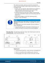
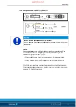
The inductive proximity switches are electronic components,
which can react sensitively to high-frequency interference or elec-
tromagnetic fields.
• Check to make sure that the cable is fastened and installed cor-
rectly. Provide for sufficient clearance to sources of high-
frequency interference and their supply cables.
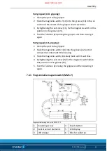
• Parallel switching of several sensor outputs of the same type
(npn, pnp) is permissible, but does not increase the permissible
load current.
• Note that the leakage current of the individual sensors
(approx. 2 mA) is cumulative.
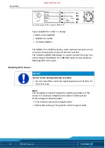
NOTICE
Blockade of the gripper after setting or replacing of the switch-
ing cam!
The switching cam can be tilt in the guide, if it was not fixed ex-
actly in the base jaw.
• Apply the switching cam in the direction of the base jaw, so
that the cam does not contact the housing of the gripper.
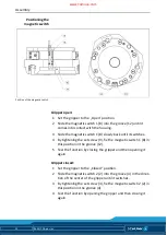
The switching points of the “open” and “closed” position were set
at the factory by SCHUNK.
Gripper open:
1 Push the proximity switch 1 (14) to the stop in the bracket (17)
2 Fasten the proximity switch by tightening the screw (13).
3 Set the gripper to the »Open« Position and test the function.
Mounting of the
proximity switch
www.comoso.com
Содержание PZB-plus
Страница 40: ...40 06 00 PZB plus en www comoso com ...


