


9
Montage- und Betriebsanleitung für Schwenkkopf
Type PSK 45, PSK 57-N/1, PSK 57-N/2
Assembly and Operating Manual for Swivel Head
Type PSK 45, PSK 57-N/1, PSK 57-N/2
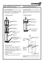
10.2 Aus- und Einbau eines Stoßdämpfers
HINWEIS:
Die Stoßdämpfer werden einem Prüfverfahren unterzogen und
mit der Prüfnummer G 141 versehen. In allen Einheiten mit Stoß-
dämpfern dürfen nur Stoßdämpfer mit Prüfnummer verwendet
werden. Die Stoßdämpfer können Sie über die Fa. SCHUNK
beziehen.
Aus- und Einbau bei PSK 45
(Pos.-Nr. siehe Kapitel 12. Explosionszeichnung)
1. Deckel (Pos. 37) abnehmen.
2. Sicherungsring (Pos. 86) entfernen.
3. Stoßdämpfer (Pos. 30) mit Passscheiben (Pos. 92 und 93)
entnehmen.
4. Einbau in umgekehrter Reihenfolge.
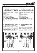
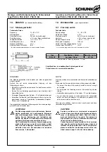
Aus- und Einbau bei PSK 57-N
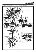
(Pos.-Nr. siehe Kapitel 12. Explosionszeichnung und Bild unten)
1. Deckel (Pos. 3 bzw. 37) abnehmen.
2. Sicherungsring (Pos. 86) entfernen.
3. Druckstück (Pos. 103) mit Scheibe (Pos. 101) und Feder
(Pos. 106) entnehmen.
4. Stoßdämpfer (Pos. 30) aus Kolben (Pos. 2) entnehmen.
5. Einbau in umgekehrter Reihenfolge.
6. Beschädigen Sie beim Einbau nicht die Dichtung (Pos. 105).
10.2 Assembly and disassembly of a shock
absorber
NOTE:
The shock absorbers are controlled and are provided with the
control number G 141. For all units equipped with shock absor-
bers, shock absorbers should be used with a control number.
These shock absorbers are available at SCHUNK.
Assembly and Disassembly for PSK 45
(For Pos.-No. see chapter 12. Drawings)
1. Remove the cover (Pos. 37).
2. Remove the safety ring (Pos. 86).
3. Remove the shock absorber (Pos, 30) together with the fitting
disks (Pos. 92 and 93).
4. Assembly is done in reverse order.
Assembly and Disassembly for PSK 57-N
(For Pos.-No. see chapter 12. Drawings and illustration below)
1. Remove the cover (Pos. 3 or 37).
2. Remove the safety ring (Pos. 86).
3. Remove the pressure piece (Pos. 103) together with the disk
(Pos. 101) and the spring (Pos. 106).
4. Take out the shock absorbers (Pos. 30) from the piston
(Pos. 2).
5. Assembly is done in reverse order.
6. Don’t damage the seal (Pos. 105) during assembly.
10.3 Montage von Kolben und Dichtungen
Montage bei PSK 45
Die Kolbendichtungen beim Schwenkkopf PSK 45 sind Lippen-
dichtringe. Diese Lippendichtringe können von Hand ohne
spezielle Vorrichtung montiert werden.
Bitte achten Sie darauf, dass beim Einführen der Kolben in das
Gehäuse und beim Überfahren der Ritzelbohrung keine
Dichtungen abgeschert werden!
Montage bei PSK 57-N
Die Kolbendichtungen beim Schwenkkopf PSK 57-N sind als O-
Ring unterstützte Glyd-Ringe ausgeführt. Diese Dichtungen müs-
sen mit speziellen Montagevorrichtungen auf die Kolben aufge-
zogen und kalibriert werden.
(Konstruktionszeichnungen zum Bau dieser Montagevor-
richtungen sehen sie in Kapitel 11).
10.3 Assembly of pistons and seals
Assembly for PSK 45
The piston seals of the swivel head PSK 45 are lip seals. These
lip seals may be assembled manually without any special assem-
bly device.
Please take care that the seals won’t be sheared off during
insertion of the piston into the housing or when crossing the
pinion bore!
Assembly for PSK 57-N
The piston seal of the swivel head PSK 57-N are O-rings
supported by Glyd-rings. These seals have to be mounted with
a special assembly device onto the piston and have to be
calibrated then.
(For drawings to build such an assembly device see chapter 11).
86
2
30
103
101
105
106


