6
Montage- und Betriebsanleitung für Schwenkkopf
Type PSK 45, PSK 57-N/1, PSK 57-N/2
Assembly and Operating Manual for Swivel Head
Type PSK 45, PSK 57-N/1, PSK 57-N/2
6.
Luftanschluss
ACHTUNG!
Beim Anschließen muss die Energieversorgung ab-
geschaltet sein. Beachten Sie auch die Sicherheits-
hinweise auf den Seiten 3 und 4.
Die Luftanschlüsse für die Schwenkbewegung sind mit Drossel-
rückschlagventilen ausgerüstet. Diese dienen zur Einstellung der
Drehgeschwindigkeit die am fertig montierten System eingestellt
werden muss.
Druckmittel: Druckluft
Anforderung an die Güteklasse der Druckluft nach DIN
ISO 8573-1: Güteklasse 4.
Interne Energiedurchführung:
(Pos.-Nr. siehe Kapitel 12. Explosionszeichnung)
Die Anschlüsse für die interne Energiedurchführung sind ge-
kennzeichnet (Nr. 1 – 8). Für den Direktanschluss werden 16 O-
Ringe (Pos. 51) mitgeliefert. Für PSK 45 in der Größe Ø 4 x 1,5
(empfohlene Senkung: Ø 7 x 1 tief) und für PSK 57-N Ø 6 x 2
(empfohlene Senkung: Ø 10 x 1,4 tief).
7.
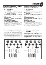
Anschlussplan der 4-fach Verteiler
(Pos.-Nr. siehe Kapitel 12. Explosionszeichnung)
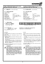
Zum Übertragen von elektronischen Signalen sind die
Schwenkköpfe PSK 45 und PSK 57-N jeweils mit 8 dreipoligen
Kupplungsdosen (Pos. 113) sowie 2 integrierten Kabeln (Pos.
110, Pos. 111) ausgestattet (je 1 Kabel für 4 Kupplungsdosen).
Die Kupplungsdosen befinden sich in den Verteilerkästen (Pos.
27) die seitlich am Schwenkkörper (Pos. 21) sitzen. Die Kabel
führen durch die Bohrung in der Lagerwelle aus dem PSK.
6.
Air connection
CAUTION!
During connection, the power supply must be swit-
ched off. Please observe the safety instructions on
pages 3 and 4.
The air connections for the swivel movement are equipped with
one-way restrictors. These are used for adjustment of the rotatio-
nal speed which has to be adjusted on the ready mounted
system.
Pressure medium: compressed air
Requirements to compressed air according to DIN ISO
8573-1: class 4.
Internal energy supply:
(For Pos.-No. see chapter 12. Drawings)
The connections for the internal energy suply are marked (No.
1 – 8). For direct connection 16 O-rings (Pos. 51) out of the little
plastic bag are used. For PSK 45 they have the size of Ø 4 x 1.5
(recommended countersunk: Ø 7 x 1 deep) and for PSK 57-N
Ø 6 x 2 (recommended countersunk: Ø 10 x 1.4 deep).
7.
Connection diagram for 4-fold
distributors
(For Pos.-No. see chapter 12. Drawings)
For transmission of electric signals, the swivel heads PSK 45 and
PSK 57-N are equipped with 8 3-poles coupler sockets (Pos. 113)
as well as with 2 integrated cables (Pos. 110, Pos. 111)
(one each cable for 4 coupler sockets). The coupler sockets are
situated inside the distributing boxes (Pos. 27), laterally at the
swivelling body (Pos. 21). The cables lead out of the bore of the
PSK into the pinion.
+
out
–
+
out
–
1
PNP
2
PNP
+
out
–
7
PNP
+
out
–
8
PNP
braun / brown
grau / grey
Last / Load 1
Last / Load 2
Last / Load 7
Last / Load 8
0V
0V
0V
0V
weiß / white
gelb / yellow
grün / green
rosa / pink
N 1
N 2
N 8
N 7
+ 24 V
0V
+
out
–
+
out
–
3
PNP
4
PNP
+
out
–
5
PNP
+
out
–
6
PNP
braun / brown
grau / grey
Last / Load 3
Last / Load 4
Last / Load 5
Last / Load 6
0V
0V
0V
0V
weiß / white
gelb / yellow
grün / green
rosa / pink
N 3
N 4
N 6
N 5
+ 24 V
0V
Kabel 1 /
Cable 1
Kabel 2 /
Cable 2

