


18
Montage- und Betriebsanleitung für Schwenkkopf
Type PSK 45, PSK 57-N/1, PSK 57-N/2
Assembly and Operating Manual for Swivel Head
Type PSK 45, PSK 57-N/1, PSK 57-N/2
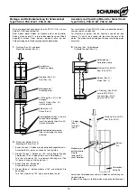
HINWEIS:
Die Näherungsschalter sind Zubehör und müssen gesondert
bestellt werden.
Achten Sie auf einen sachgemäßen Umgang mit den
Näherungsschaltern:
– Ziehen Sie nicht am Kabel und lassen Sie den Sensor nicht am
Kabel baumeln.
– Ziehen Sie die Befestigungsschraube oder -klemmen nicht
übermäßig fest an.
– Zulässiger Biegeradius des Kabels = 15 x Kabeldurchmesser.
– Vermeiden Sie Kontakt der Näherungsschalter zu harten Ge-
genständen, sowie zu Chemikalien, insbesondere Salpeter-,
Chrom- und Schwefelsäure.
Die eingesetzten induktiven Näherungsschalter sind verpolungs-
geschützt und kurzschlussfest.
ACHTUNG!
Die Näherungsschalter sind elektronische Bauteile,
welche empfindlich auf hochfrequente Störungen
oder elektromagnetische Felder reagieren können.
Prüfen Sie die Anbringung und Installation des
Kabels. Der Abstand zu hochfrequenten Störquellen
und deren Zuleitung muss ausreichend sein.
Das Parallelschalten mehrerer Sensorausgänge der
gleichen Bauart (npn, pnp) ist zwar erlaubt, erhöht
aber nicht den zulässigen Laststrom. Beachten Sie
weiterhin, dass sich der Leckstrom der einzelnen
Sensoren (ca. 2 mA) addiert.
NOTE:
Proximity switches are accessories and have to be ordered sepa-
rately.
Make sure that the proximity switches will be properly handled:
– Do not pull the wire of the proximity switch and don’t swing it
on its cable.
– Do not tighten the fastening screw or the anchoring clip too
strong.
– Admissible bending radius of the cable = 15 x cable diameter.
– Do not allow the sensor to make contact with a detectable
object of a hard substance or to chemicals, especially nitric
acid, chromic acid and sulfure acid.
The proximity switches used are short circuit proof and have
reverse battery protection.
CAUTION!
Proximity switches are electronical components
which can react sensitively to high frequency interfe-
rence or electromagnetic fields. Check the attach-
ment and installation of the cable. The distance to
high frequency sources to interference and their feed
lines has to be sufficiently long.
Connecting several sensor outputs of the same type
(npn, pnp) in parallel is allowed, however it does not
increase the permissible load current. Furthermore,
please consider that the leakage current of the indi-
vidual sensors (appr. 2 mA) has to be added up.
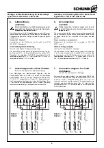
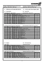
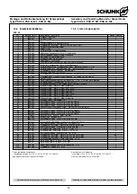
Type
Schaltfunktion / Output
Ident-Nr. / Id.-No.
INW 80/S
Schließer / Closer
301 508
Schaltabstand / Sensing distance: 1.5 mm
Schaltfunktion: in unbedämpftem Zustand gezeichnet
Output: drawn in non-actuated condition
2 Stück / 2 pieces
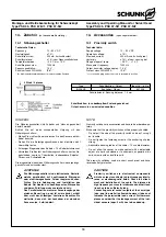
14. Zubehör
(auf besondere Bestellung)
14.1 Näherungsschalter
Technische Daten:
Spannung:
10 – 30 V DC
Restwelligkeit:
≤
15%
Schaltstrom max.:
200 mA, kurzschlussfest
Schalthysterese:
≤
15% vom Nennschaltabstand
Temperaturbereich:
– 25° C bis + 70° C
Schaltfrequenz max.:
1000 Hz
Spannungsabfall ca.:
1,5 V
Schutzart nach DIN 40050:
IP 67*
* für die Rundsteckverbindung nur im verschraubten Zustand
14. Accessories
(upon separate order)
14.1 Proximity switch
Technical data:
Supply voltage:
10 – 30 V DC
Operation voltage:
≤
15%
Max load current:
200 mA, short circuit proof
Hysterisis:
≤
15% of nom. sensing dist.
Range of operat. temp.:
– 25° C ... + 70° C
Max operat. frequency:
1000 Hz
Output transistor voltage approx.: 1.5 V
Protect. class DIN 40050:
IP 67*
* for concentric plug and socket only in screwed-in position


