


10
Montage- und Betriebsanleitung für Schwenkkopf
Type PSK 45, PSK 57-N/1, PSK 57-N/2
Assembly and Operating Manual for Swivel Head
Type PSK 45, PSK 57-N/1, PSK 57-N/2
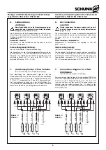
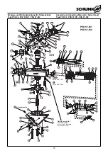
Bei der doppelt beaufschlagten Version PSK 57-N/2 sind pro
Kolben 2 Dichtringe erforderlich.
Beim Einbau dieser Kolben ins Gehäuse muss ein spezieller
Bolzen (siehe Kapitel 11) in die Aufnahmebohrung des Ritzels
eingeführt werden. Diser Bolzen verhindert, dass bei der
Kolbenmontage die Dichtungsringe beschädigt werden.
For swivel heads of type PSK-N/2, which are double-actuated, 2
seals per piston are required.
For assembly of pistons into the housing a special pin (see
chapter 11) has to be inserted into the mounting bore of the
pinion. This pinion avoid a damage of the seal ring during piston
assembly.
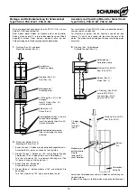
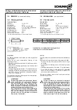
1.
Dichtung (Pos. 40) aufziehen
Mount the sealing (Pos. 40)
2.
Dichtung (Pos. 40) kalibrieren
Calibrate the seal (Pos. 40)
3.
Einbau der Kolben (Pos. 2)
Mounting of Piston (Pos. 2)
Anstatt des Fixierbolzens kann der 2. Kolben ohne Dichtung ver-
wendet werden /
Instead of the fixing pin, the 2nd piston may be used without seal.
Spreizhülse /
Expansion sleeve
Dichtung (Pos. 40) /
Seal (Pos. 40)
Montagekegel /
Assembly taper
2 O-Ringe (Pos. 41) in Nut
einlegenl /
Insert 2 O-rings (Pos. 41)
into the groove
Kolben (Pos. 2) /
Piston (Pos. 2)
1. Kolben
(Pos. 2) /
1st piston
(Pos. 2)
Bolzen /
Pin
Fixierbolzen /
Fixing Pin
Dichtung (Pos. 40/41) /
Seal (Pos. 40/41)
Dichtung (Pos. 40/41) /
Seal (Pos. 40/41)
Kolben (Pos. 2) /
Piston (Pos. 2)
2. Dichtung (Pos. 40/41)
nur bei PSK 57-N/2 /
2nd seal (Pos. 40/41)
only for PSK 57-N/2
Kalibrierhülse /
Calibration sleeve
Führungsbänder (Pos. 42) in die
flachen Nuten einlegen /
Insert the guiding tape (Pos. 42)
into the flat groove
1. Bauen Sie den 1. Kolben wie nebenstehend abgebildet ein /
Assemble the 1st piston as shown on the right side.
2. Drehen Sie den 1. Kolben um 180° und entfernen Sie den
Fixierbolzen. (Der 1. Kolben dient nun als Fixierbolzen) /
Turn the 1st piston by 180 ° and remove the fixing pins. (The
1st piston is used as a fixing pin now!)
3. Bauen Sie den 2. Kolben ein /
Assemble the 2nd piston.
4. Drehen Sie den 1. Kolben wieder um 180° und entfernen Sie
den Bolzen
Turn the 1st piston by 180 ° again and remove the pin.
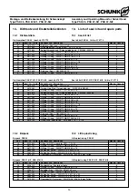
Stoßdämpferentnahmeseite /
Side for removing the shock
absorber
Stoßdämpfer-
entnahmeseite /
Side for
removing the
shock absorber


