Assembly
24
17.00 | KGG | Assembly and Operating Manual | en | 389166
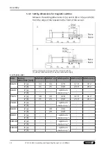
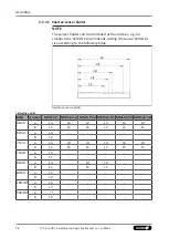
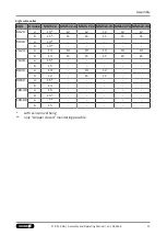
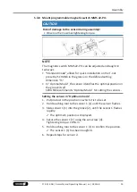
5.3.3 Setting dimensions for magnetic switches
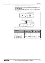
Measure the setting dimensions l1 (a) and l1 (b) or l2 (a) and l2 (b)
from the edge of the bracket to the front of the sensor.
Setting dimensions l1 (a) and l1 (b) or l2 (a) and l2 (b)
(A: view of cable outlet left; B: view of cable outlet right)
A: Left cable outlet
KGG
Setting
dimension [mm]
MMS 22-A MMS-P 22 MMS 22-PI1 MMS 22-PI2 MMS 22-IOL
60-20
l2 (a)
34
34
37.9
37.9
37.2
l2 (b)
21
21
24.9
24.9
24.2
60-40
l2 (a)
-
-
optimum
mode only *
-
-
l2 (b)
-
-
-
-
70-24
l2 (a)
38
39
41.9
41.9
41.2
l2 (b)
21
23
24.9
24.9
24.2
70-48
l2 (a)
-
-
optimum
mode only *
-
-
l2 (b)
-
-
-
-
80-30
l2 (a)
-
38
39.4
-
-
l2 (b)
-
20
23.9
-
-
80-60
l2 (a)
-
-
optimum
mode only *
-
-
l2 (b)
-
-
-
-
100-40
l2 (a)
-
-
optimum
mode only *
-
-
l2 (b)
-
-
-
-
100-80
l2 (a)
-
-
optimum
mode only *
-
-
l2 (b)
-
-
-
-
Содержание KGG 100
Страница 1: ...Translation of the original manual Assembly and Operating Manual KGG 2 Finger Parallel Gripper...
Страница 49: ......
Страница 50: ......
Страница 51: ......

