45
AIR COMPRESSOR - OWNER'S MANUAL
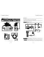
TECHNICAL DATA 20120HWV80X
4
3
2
6
7
11
10
3
4
2
18
16
33
19
25
26
18
27
28
30
1
38
37
31
21 - 45
34
24
23
14
20
20
9
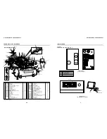
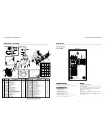
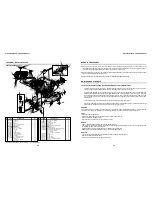
AIR COMPRESSOR PARTS
2 x 1 reduction bushing
1/4 tube
Centrifugal unloading valve
Centrifugal unloading valve kit
Motor 208/230/460V (three-phase)
Belt
Motor fastening plate
7/16 x 1.3/4 hex head bolt
7/16 hex nut
1/2 lock washer
1/2 washer
Pulley
3/8 x 1/2 Allen hex without head
Start switch**
Support start switch**
Start switch pressure switch cord (not shown)**
Motor start switch cord (not shown)**
3/4 NPT air filter
Filter element
Hose for tank drain (not shown)
CODE
QTY
DENOMINATION
01
01
01
01
01
02
02
04
04
08
08
01
01
01
01
01
01
03
03
01
No.
26
27
28
29
30
31
32
33
34
35
36
37
38
39
40
41
42
43
44
45
Bare pump
3/4 nipple
NPT 3/4 x 1/2 straight connection
Upper tubing adaptor
Belt guard
Pressure gauge
Pressure switch
1/4 nipple
Strain relief
1/4 ASME safety valve
3/4 x 126mm nipple
3/4 side elbow
3/4 plug
Check valve
Check valve kit
NPT 1/8 x 1/4 straight connection
2 Plug
O - ring
1/4 tank drain valve
W 1/2 x 1.1/2 hex head bolt
BSW 1/2 hex nut
120 gal horiz. Tank
CODE
QTY
DENOMINATION
933.9385-0
003.0036-5
21011001
20517005
830.1023-0
011.0118-0
012.0845-0
003.0174-4
012.0723-0
022.0057-0
21011006
003.0343-0
003.0031-4
60281501
34004508
003.0054-3
003.0514-0
023.0339-0
022.0185-0
*
*
25003832A
01
02
04
02
01
01
01
01
01
01
01
01
01
01
01
01
01
02
01
04
04
01
No.
1
2
3
4
6
7
8
9
10
11
13
14
15
16
17
18
19
20
21
23
24
25
003.0512-0
709.1671-0
022.0174-0
830.1043-0
015.0604-0
004.0022-0
21028539
*
*
*
*
709.1349-0
*
012.0941-0
701.0381-0
012.0907-0
012.0910-0
809.1085-0
007.0118-0
709.1246-0
* Part available in the market - not sold by Schulz.
** Optional start switch
29
39
36
15
35
35
36
40
44
43
17
8
13
32
AIR COMPRESSOR - OWNER'S MANUAL
4
INSTALLATION
Wiring -
pressure switch
Before starting the installation procedure, check that the building's electrical service has an adequate
capacity to handle the motor and the same electrical characteristcs (voltage, cycle, and phase). Install the compressor
as close to the main power supply as possible and follow all National Electric Safety Codes as well as those dictated
by State and Local authorities. A qualified electrician must do the electrical installation. Every compressor model has a
specific power requirement and the wire size used is critical to a proper installation. The two tables (shown below) are
for reference only and should not supersede specific National, State or Local code requirements. The compressor can
be mannufactured without a
, according to the product version.
power switch
The
must not be
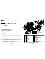
directly connected to the motor but to a control circuit. See "Electrical Diagram" page 5 and 6 to correct
installation, according to the product version.
Piping -
The main distribution line should not be any smaller than the pipe size of the shut off valve of the compressor. It is
recommended that the shop air system be connected to the air compressor shut off valve with a flexible coupler to reduce
the risk of damage from vibration. All airlines should slope to an accessible drain or moisture trap for removal of
condensation. Make sure that there are no leaks in the airlines as even small leaks can cause your compressor to run
outside of the rated duty cycle. A typical installation is shown on page 11, note that the feeder lines come off of the top of the
main distribution line so that moisture can't enter the feeder line.
WARNING
!
ASME coded pressure vessels must not be modified, welded, repaired, reworked or
subjected to operating conditions outside the nameplate ratings. Such actions will negate
code status, affect insurance status and may cause severe personal injury, death and
property damage.
DANGER
!
High voltage may cause personal injury or death. Disconnect and lockout/tagout per
O.S.H.A. Regulation 1910.147 all electrical power supplies before opening the electrical
enclosure or servicing.
30 amp circuit
0-30 ft.
31-50 ft.
51-70 ft.
10 ga
8 ga
6 ga
71 ft and up:
call factory
40 amp circuit
0-25 ft.
26-50 ft.
51-75 ft.
8 ga
6 ga
4 ga
76 ft and up:
call factory
60 amp circuit
0-10 ft.
11-30 ft.
31-50 ft.
8 ga
6 ga
4 ga
51 ft and up:
call factory
Air Intake -
Do not locate the compressor where it could ingest toxic, volatile or corrosive vapors or extremely dirty air. If a
remote inlet filter is going to be installed you must increase one pipe size for every ten feet in length and use a flex hose
between the pump and any solid pipe to minimize the potential of damage from vibration.
Grounding instructions:
This product must be
grounded to reduce the risk of an electric shock. Connect
the Grounding cable to the motor's terminal, or if there is
no terminal to the motor's frame.
The incorrect installation of the grounding wire connector may result in an electric shock. If it is
necessary to replace or repair both the cable and the connector, do not connect or join the grounding wire
to the neutral wire or other. The green wire, with or without yellow stripes, is only to the grounding
function. In case of doubts regarding the grounding information or whether the product is properly
grounded, make sure you contact a qualified electrician to verify the connections.
WARNING
Motor power [ hp ]
single-phase
three-phase
Input supply
voltage [V]
Max.fuse
(gL/gG)* [A]
3
5
-
7.5
-
-
-
-
-
-
-
-
-
-
5
-
7.5
7.5
10
10
15
15
20
20
230
230
460
230
230
460
230
460
230
460
230
460
50
35
20
80
50
25
63
35
100
50
100
63
Orientative table for fuses
* type 2 coordination
Orientative table for wiring


