


3
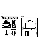
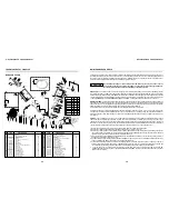
DESCRIPTION OF OPERATION
Tank Drain Valve
Intake Air Filter
ON / OFF Switch
Pressure Gauge
SHUT OFF Valve
Cooling System
- This valve, also known as a petcock, is to drain out any condensation in the tank. Since some moisture
will form inside the tank every time the compressor runs, it is important to drain the tank daily.
- As air is drawn into the compressor pump it must pass through a filter to remove dirt and dust. When the
filter element becomes clogged with dirt it creates a high vacuum condition in the cylinder which can cause the oil from the
crankcase to be sucked up past the rings and into the tank.
- Starts and stops the air compressor. It is important to remember that in the
“
On
”
position, the compressor
can start automatically. The compressor should not be turned off in mid-cycle using the switch (except in an emergency) so
that the pressure switch is allowed to relieve the head pressure when it tums off the compressor.
- The pressure gauge reads the air pressure in the tank or air system.
- A ball or gate valve that is installed on the tank where the air is going out to the shop air system. This
valve is used during scheduled maintenance to separate the compressor from the rest of the air system. It could also be
important to quickly shut off the air from the tank in case of a problem like an airline breaking.
- Air compressor pumps create remarkable amount of heat as they operate. Because so much heat is
generated, the cooling system of the compressor is critical to the life of the pump. Compressor pumps are heavily finned to
dissipate heat. Cooling air is blown over the fins by the fan blades designed into the flywheel of the pump. The inter cooler
and after cooler lower the air temperature significantly, thereby making it easier to compress the air.
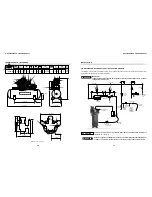
INSTALLATION
Location -
The air compressor should be installed in a clean, dry, well lighted, and well ventilated area on a level floor. The
flywheel side of the compressor should be towards the wall and the distance between the compressor and the wall should
be a minimum of 30
”
to allow for proper cooling air circulation, inspections, and maintenance.
Mounting -
Your compressor must be installed according to all applicable State and Local Laws. Shims may be needed to
level the legs. Care must be taken when tightening anchor bolts. Uneven torque can lead to excessive vibration that can
weaken welds and cause explosions. Tighten three leveled legs equally and leave the fourth nut loose.
WARNING
!
Under no circumstances
a compressor be placed in an area that may be exposed to a
toxic, volatile or corrosive atmosphere nor should toxic, volatile or corrosive agents be
stored near the compressor.
should
AIR COMPRESSOR - OWNER'S MANUAL
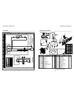
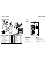
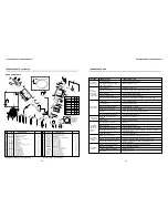
SYSTEM COMPONENTS
Pressure Switch
Check Valve
Pressure Relief Valve
- The pressure switch senses the air pressure in the system and automatically starts the motor when the
pressure drops below the cut in setting.
Once the pump builds the pressure up to the maximum or cut out pressure, the pressure switch shuts off the motor and
bleeds down the air pressure between the pump and check valve. This allows the motor to restart in an unloaded mode.
- The check valve is a device that allows the air to flow in only one direction. While the compressor is running,
the check valve is
“
open
”
, allowing the air to flow from the pump to the tank. When the compressor stops, the check valve is
“
closed
”
and keeps the air in the tank from trying to back up to the pump.
- This valve is often called a
“
pop-off
”
or a
“
safety relief valve
”
. Its job is to open up and relieve the air
pressure in the event the pump did not shut off at the maximum setting.
AIR COMPRESSOR - OWNER'S MANUAL
46
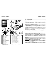
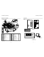
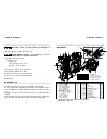
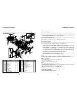
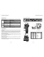
TECHNICAL DATA 20120HWV80X
BARE PUMP PARTS
28
27
4
26
25
24
23
21
12
62
11
7
5
3
12
9
8
2
1
4
6
10
22
4
29
19
20
20
17
18
4
35 - 34 - 33
32 - 31 - 30
15
16
14
13
12
A
28**
37 38 39
8
T5
T3
T2
T6
T7
T4
T2
ASSEMBLY OF INTERCOOLERS
54
51
50
65
Upper gasket kit
LP 4.3/4" cylinder
HP 90mm cylinder
HP 2.1/2" cylinder
LP 4.3/4" valve plate kit
HP 90 mm valve plate kit
LP 4.3/4" valve plate
HP 90mm valve plate
HP 2.1/2" valve plate
LP 4.3/4" cylinder cover (with breather)
LP 4.3/4" cylinder cover (without breather)
HP 90mm cylinder cover
HP 2.1/2" cylinder cover
UNC 3/8" x 1.1/2" head bolt
Short intercooler No. 2
Medium intercooler No. 3
Long intercooler No. 4
3/4" nut for intercooler
Intercooler holder
1/4" crankcase breather tube
1/8" x 1/4" straight connection
1/4" ring kit
HP 5/16" x 1.1/2" Allen hex bolt
HP 2.1/2" valve plate kit
Washer kit
M6 x 1 x 55 Allen hex bolt
Connecting rod with needle bearing
Needle bearing
LP 1/8" ASME safety valve
Intercooler kit without tube No. 1 (item 66)
Discharge tube No. 1
Discharge tube No. 5
HP 1/8" ASME safety valve
3/4" x 3/4
”
straight connection
01
03
01
01
03
01
03
01
01
01
02
01
01
23
01
01
01
10
03
01
01
01
06
01
01
08
01
02
03
01
01
01
02
06
36
37
38
39
40
41
42
43
44
45
46
47
48
49
50
51
52
53
54
55
56
57
58
59
60
61
62
63
64
65
66
67
68
69
830.1031-0/NA
709.1306-0
709.1308-0
709.1347-0
830.0955-0
830.1002-0
809.1028-0
809.1027-0
809.1029-0
709.1272-0
709.1423-0
709.1424-0
709.1389-0
*
709.1457-0
709.1459-0
709.1458-0
21011004
21029003
830.0340-5
003.0054-3
830.0599-8
383.0111-0
830.0957-0
830.1032-0
013.0752-0
830.1202-0
019.0079-0
022.0177-0
809.1043-0
709.1369-0
709.1456-0
022.0215-0
21011002
Flywheel
UNC 1/4" x 3/4" head bolt
Flange cover
Crankcase gasket kit
Oil seal
Lock washer and nut kit
33109 bearing
NC 1/2" x 1" head bolt
Straight fitting
Flange
32211 bearing
Crankshaft kit
Key
UNF 3/8" x 3" head bolt
Crankshaft counter weight
Connecting rod pin kit
Connecting rod
Master connecting rod
Connecting rod inner bushing
Connecting rod bushing
Counter weight with centrifugal mechanism
Counter weight kit with centrifugal mechanism
UNF 5/16" x 1.1/4" Allen head bolt
Crankcase
3/8" plug
3/4" oil level sight kit
Crankcase cover
UNC 5/16" x 3/4" head bolt
3/4" plug
LP 4.3/4" piston
HP 90mm piston kit
HP 2.1/2" piston kit
LP 4.3/4" ring kit
HP 90mm ring kit
HP 2.1/2" ring kit
01
04
01
01
01
01
01
26
01
01
01
01
01
02
01
04
03
01
02
07
01
01
02
01
01
01
01
06
01
03
01
01
03
01
01
1
2
3
4
5
6
7
8
9
10
11
12
13
14
15
16
17
18
19
20
21
22
23
24
25
26
27
28
29
30
31
32
33
34
35
709.1346-0
*
20505001
830.1033-0/NA
60082501
830.0932-0
60154502
*
60259501
20504001
60154501
830.0933-0
60267503
*
20508005
830.0934-0
30008502
830.0938-0
60152502
60152501
30007007
830.0937-0
*
20501001
003.0029-2
830.0775-0
709.1316-0
*
003.0031-4
60273501
830.1000-0
830.0939-0
000.0077-0
000.0080-0
000.0075-0
CODE
CODE
QTY
QTY
DENOMINATION
DENOMINATION
No.
No.
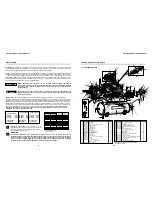
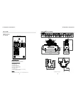
* Part available in the market - not sold by Schulz
Note: HP = high pressure LP = low pressure
TABLE 1 - TORQUE
ESPECIFICATION FOR BOLTS
T7
T10
T11
T6
T9 HP-LP 40-41-59
LP 40-41-59
T5
T8
T4
T3
T2
T1
Position
lbf.in
304
49
704
8
70
2
158
28
1,215
12
141
61
334
14
19
185
23
44
264
58
30
34
80
8
18
137
16
38
2.2
21
5
N.m
57
55
9
56
B
A
66
67 65
52
53
69
64
64
64
68
68
63
** See code page 44
49 58
44**
43**
61
60 59 41 40
36
44 43 42
40 41 59
40 41 59
48 47 46 45
36
B
T1
T8
T9
T9
T10
T11
ft.lb
25
58
5.8
13
101
27.8
15
12
1.6
3.6
22