background image

GB

14

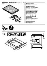
Front

Hooking position

Back

for top H=40 mm

! Use the hooks contained in the “accessory pack”

• Where the hob is not installed over a built-in oven, a

wooden panel must be installed as insulation. This must
be placed at a minimum distance of 20 mm from the
lower part of the hob.

Ventilation

To ensure adequate ventilation, the back panel of the
cabinet must be removed. It is advisable to install the oven
so that it rests on two strips of wood, or on a completely
flat surface with an opening of at least 45 x 560 mm (

see

diagrams).

! The hob can only be installed above built-in ovens with a
cooling ventilation system.

Electrical connection

Hobs equipped with a three-pole power supply cable are
designed to operate with alternating current at the voltage
and frequency indicated on the data plate (this is located
on the lower part of the appliance). The earth wire in the
cable has a green and yellow cover. If the appliance is to
be installed above a built-in electric oven, the electrical
connection of the hob and the oven must be carried out
separately, both for electrical safety purposes and to make
extracting the oven easier.

Connecting the supply cable to the mains

Install a standardised plug corresponding to the load
indicated on the data plate.
The appliance must be directly connected to the mains
using an omnipolar circuit-breaker with a minimum contact
opening of 3 mm installed between the appliance and the
mains.  The circuit-breaker must be suitable for the charge
indicated and must comply with current electrical regulations
(the earthing wire must not be interrupted by the circuit-

breaker). The supply cable must not come into contact with
surfaces with temperatures higher than 50°C.

! The installer must ensure that the correct electrical
connection has been made and that it is compliant with
safety regulations.
Before connecting to the power supply, make sure that:

• The appliance is earthed and the plug is compliant with

the law.

• The socket can withstand the maximum power of the

appliance, which is indicated on the data plate.

• The voltage is in the range between the values indicated

on the data plate.

• The socket is compatible with the plug of the appliance. If

the socket is incompatible with the plug, ask an
authorised technician to replace it. Do not use extension
cords or multiple sockets.

! Once the appliance has been installed, the power supply
cable and the electrical socket must be easily accessible.

! The cable must not be bent or compressed.

! The cable must be checked regularly and replaced by
authorised technicians only (

see Assistance).

! The manufacturer declines any liability should these
safety measures not be observed.

Gas connection

The appliance should be connected to the main gas
supply or to a gas cylinder in compliance with current
national regulations. Before carrying out the connection,
make sure the cooker is compatible with the gas supply
you wish to use. If this is not the case, follow the
instructions indicated in the paragraph “Adapting to
different types of gas.”
When using liquid gas from a cylinder, install a pressure
regulator which complies with current national regulations.

! Check that the pressure of the gas supply is consistent
with the values indicated in Table 1 (“Burner and nozzle
specifications”). This will ensure the safe operation and
longevity of your appliance while maintaining efficient
energy consumption.

Connection with a rigid pipe (copper or steel)

! Connection to the gas system must be carried out in
such a way as not to place any strain of any kind on the
appliance.
There is an adjustable L-shaped pipe fitting on the
appliance supply ramp and this is fitted with a seal in
order to prevent leaks. The seal must always be replaced
after rotating the pipe fitting (seal provided with
appliance). The gas supply pipe fitting is a threaded 1/2
gas cylindrical male attachment.

Connecting a flexible jointless stainless steel pipe to a
threaded attachment

560 mm.

45 mm.

Содержание TGL 640

Страница 1: ...tta caratteristiche Caretteristiche dei bruciatori ed ugelli Descrizione dell apparecchio 6 Vista d insieme Avvio e utilizzo 7 Consigli pratici per l uso dei bruciatori Precauzioni e consigli 8 Sicure...

Страница 2: ...i i locali contenenti bidoni di GPL debbono prevedere delle aperture verso l esterno cos da permettere l evacuazione dal basso delle eventuali fughe di gas Pertanto i bidoni di GPL siano essi vuoti o...

Страница 3: ...rsi che la presa abbia la messa a terra e sia a norma di legge la presa sia in grado di sopportare il carico massimo di potenza della macchina indicato nella targhetta caratteristiche la tensione di a...

Страница 4: ...rimettere in posizione tutti i componenti seguendo le operazioni inverse rispetto alla sequenza di cui sopra Regolazione aria primaria dei bruciatori I bruciatori non necessitano di nessuna regolazio...

Страница 5: ...79 95 Tripla Corona TC 130 3 30 1 30 57 87 240 236 3 60 131 343 Ultra Rapido UR 100 3 40 0 70 40 91 247 243 3 40 123 324 Doppie Fiamme DCDR Interno 30 0 90 0 40 30 44 65 64 0 90 74 86 Doppie Fiamme DC...

Страница 6: ...GAS BRUCIATORI GAS sono di diverse dimensioni e potenze Scegliete quello pi adatto al diametro del recipiente da utilizzare Manopole di comando dei BRUCIATORI GAS per la regolazione della fiamma o de...

Страница 7: ...utte le dimensioni in questo caso per piccoli recipienti accendete il solo bruciatore interno Ogni singola corona che compone il bruciatore a doppie fiamme indipendenti ha una sua manopola di comando...

Страница 8: ...e rivolti verso l interno del piano cottura per evitare che vengano urtati accidentalmente Non chiudere il coperchio in vetro se presente con i bruciatori gas o la piastra elettrica ancora caldi Non l...

Страница 9: ...do cura di eliminare le eventuali incrostazioni Nei piani dotati di accensione automatica occorre procedere frequentemente ad una accurata pulizia della parte terminale dei dispositivi di accensione i...

Страница 10: ...e di minimo non rimane acceso I recipienti sono instabili Se nonostante tutti i controlli il piano non funziona e l inconveniente da voi rilevato persiste chiamate il Centro Assistenza Tecnica Comunic...

Страница 11: ...IT 11...

Страница 12: ...Data plate Burner and nozzle specifications Description of the appliance 17 Overall view Start up and use 18 19 Practical advice on using the burners Practical advice on using the the Ceramic Glass M...

Страница 13: ...to the floor as it is heavier than air Therefore rooms containing LPG cylinders must also be equipped with vents to allow gas to escape in the event of a leak As a result LPG cylinders whether partial...

Страница 14: ...pply make sure that The appliance is earthed and the plug is compliant with the law The socket can withstand the maximum power of the appliance which is indicated on the data plate The voltage is in t...

Страница 15: ...parate parts see figure 2 unscrew the burers with a 7 mm wrench spanner The internal burner has a nozzle the external burner has two of the same size Replace the nozzle with models suited to the new t...

Страница 16: ...zle 130 4 10 1 30 57 70 298 293 4 10 110 390 Supply Pressures Nominal mbar Minimum mbar Maximum mbar 28 30 20 35 37 25 45 20 17 25 At 15 C and 1013 mbar dry gas Propane P C S 50 37 MJ Kg Butane P C S...

Страница 17: ...e cookware to choose the most appropriate burner to cook with Control Knobs for GAS BURNERS adjust the power or the size of the flame GAS BURNER ignition enables a specific burner to be lit automatica...

Страница 18: ...m setting gives a very high power which reduces cooking times with respect to conventional burners Moreover the double flame crown provides a more uniform distribution of heat on the bottom of the pan...

Страница 19: ...he knob to minimum On the models supplied with a reducer shelf remember that this should be used only for the Double flame external DCDR external burner when you use casserole dishes Wook To identify...

Страница 20: ...ce Centre see Assistance Always make sure that pan handles are turned towards the centre of the hob in order to avoid accidental burns Do not close the glass cover if present when the gas burners or e...

Страница 21: ...burners should be washed frequently with warm water and soap and any burnt on substances removed For hobs which ligth automatically the terminal part of the electronic instant lighting devices should...

Страница 22: ...liance You pressed the knob all the way in You keep the knob pressed in long enough to activate the safety device The gas holes are not blocked in the area corresponding to the safety device The gas h...

Страница 23: ...es des br leurs et des injecteurs Description de l appareil 29 Vue d ensemble Mise en marche et utilisation 30 31 Conseils pratiques pour l utilisation des br leurs Quelques conseils utiles pour bien...

Страница 24: ...tionales en vigueur Pour la Belgique NBN D51 003 et NBN D51 001 en vigueur Pour le Luxembourg selon les Normes Nationales en vigueur Pour la Hollande NEN 1078 en vigueur Il faut observer les condition...

Страница 25: ...i ait une d coupe d au moins 45 x 560 mm voir figures La table ne peut tre install e qu au dessus de fours encastrables quip s de ventilation de refroidissement Raccordement lectrique Les tables munie...

Страница 26: ...d un tuyau rigide pour la Belgique selon les Normes NBN D51 003 ou d un tuyau flexible en acier inox sans interruption et quip de raccordements filet s En amont de l appareil il faut installer un robi...

Страница 27: ...d ouverture maximale et vice versa plusieurs reprises V rifiez ainsi qu il n y ait pas extinction du br leur 4 En cas de mauvais fonctionnement du dispositif de s curit gaz thermocouple quipant certai...

Страница 28: ...iaire A 55 0 40 1 00 30 50 73 71 79 1 00 95 1 00 111 Triple Couronne TC 130 1 30 3 30 57 87 240 236 131 3 60 309 3 30 360 Ultra Rapide UR 100 0 70 3 40 40 91 247 243 123 3 40 324 3 40 376 Deux flammes...

Страница 29: ...mieux au diam tre de votre casserole Manettes de commande des BR LEURS GAZ pour le r glage de la flamme ou de la puissance La bougie d allumage des BR LEURS GAZ permet l allumage automatique du br le...

Страница 30: ...sance lev e qui r duit consid rablement les temps de cuisson par rapport aux br leurs traditionnels Le double anneau de flamme permet de plus une distribution plus uniforme de la chaleur sur le fond d...

Страница 31: ...bullition Sur les mod les munis de grille de r duction voire fig cette derni re ne doit tre utilis e que sur le br leur Deux flammes ext rieur DCDR ext rieur lorsque l on utilise des r cipients WOOK...

Страница 32: ...que les manches des casseroles soient toujours tourn s vers l int rieur de la table de cuisson pour viter tout risque d accident N abaissez pas le couvercle en verre s il y en a un tant que les br leu...

Страница 33: ...d tergent en liminant soigneusement toute incrustation Dans le cas de tables quip es d allumage automatique nettoyez fr quemment et soigneusement l extr mit des dispositifs d allumage lectronique inst...

Страница 34: ...ond sur la manette vous avez bien appuy fond sur la manette pendant un laps de temps suffisant pour permettre l activation du dispositif de s curit les orifices de sortie du gaz situ s en face du disp...

Страница 35: ...FR BE NL 35...

Страница 36: ...del aparato 39 Vista de conjunto Puesta en funcionamiento y uso 40 41 Consejos pr cticos para el uso de los quemadores Precauciones y consejos 42 Seguridad general Eliminaci n Mantenimiento y cuidados...

Страница 37: ...botellas de GPL deben tener aberturas hacia el exterior para permitir la evacuaci n desde abajo de eventuales escapes de gas Adem s las botellas de GPL vac as o parcialmente llenas no deben ser insta...

Страница 38: ...unto una temperatura que supere en 50 C la temperatura ambiente El instalador es responsable de la correcta conexi n el ctrica y por el cumplimiento de las normas de seguridad Antes de efectuar la con...

Страница 39: ...o una llave tubular de 7 mm El quemador interno posee un inyector el quemador externo posee dos de la misma dimensi n Sustituya los inyectores con los adecuados al nuevo tipo de gas ver la tabla 1 3 v...

Страница 40: ...tural Quemador Di metro mm Potencia t rmica kW p c s By pass 1 100 Inyector 1 100 caudal g h Potencia t rmica kW p c s Inyector 1 100 caudal l h Nomin Reduc mm mm Nomin mm R pido R 100 3 00 0 70 40 86...

Страница 41: ...S A GAS QUEMADORES A GAS son de distintas dimensiones y potencias Elija siempre el m s adecuado para el di metro del recipiente que va a utilizar Mandos de los QUEMADORES A GAS para la regulaci n de l...

Страница 42: ...rmite una elevada potencia que disminuye los tiempos de cocci n con respecto a los quemadores tradicionales Adem s la doble corona de llama vuelve m s uniforme la distribuci n de calor en el fondo de...

Страница 43: ...mando hasta la posici n de m nimo En los modelos que poseen rejilla de reducci n ver la figura la misma deber ser utilizada s lo para el quemador Dos Llamas externo DC DR externo cuando se utilizan re...

Страница 44: ...las ollas est n siempre dirigidos hacia dentro de la encimera para evitar que sean chocados accidentalmente No cierre la tapa de vidrio si existe cuando los quemadores o la placa el ctrica todav a est...

Страница 45: ...tando siempre de eliminar las incrustaciones En las encimeras que poseen encendido autom tico es necesario realizar frecuentemente una cuidadosa limpieza de la parte terminal de los dispositivos de en...

Страница 46: ...la altura del dispositivo de seguridad Est n obstruidos los orificios de salida del gas Hay corriente de aire en las cercan as de la encimera La regulaci n del m nimo no es correcta El fondo del recip...

Страница 47: ...ES 47...

Страница 48: ...48 ES 09 2006 195053700 02 XEROX BUSINESS SERVICES...

Отзывы: