schmersal PSCBR-C-10 Series Скачать руководство пользователя страница 15

Installation manual                                                      


Page 15 of204 


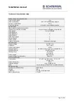
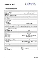
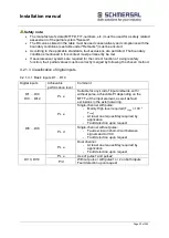
Technical characteristic data 


Safety related characteristic data 


Pl acc. to EN 13849 

Pl e 

PFH / architecture 

2,2 * 10

-9 / 

architecture class 4


SIL acc. to EN 61508 

SIL 3 

Proof test interval 

20 years = max. utilization period 

General data 


Max. number of extension modules 

Interface for extension modules 

T-bus connector, pluggable in top-hat rail 

Safe digital I 

14 incl. 8 OSSD 

Safe digital I/O 

Safe digital Out 

Safe analog In 

Safe relay outputs 

Signal outputs 

Pulse outputs 

Type of connection 

Clamp-type terminals 

Axis monitoring 

1 axis 

Encoder interface front number / technology 

1 / SSI; SIN/COS; Incr.-TTL


Max. frequency SIN/COS, Incr. TTL 

200 kHz 

Cycle frequency/mode SSI 

Master mode 150 kHz / Slave mode max. 250 kHz 

Type of connection 

D-SUB 9pole 

Encoder interface terminals number / 
technology 

1 / Proxi-Sw.; Inc.-HTL 

Max. frequency Proxi 

10 kHz 

Type of connection 

Clamp-type terminals 

Electrical data 


Supply voltage 

24 VDC / 2A 

Tolerance 

-15%, +20% 

Power consumption 

2.4 W 

Ratings digital I 

24 VDC; 20 mA, Type1 acc. to EN61131-2 

Ratings digital O 

 24VDC; 250 mA 

Ratings relays 

24 VDC/2A 

230 VAC/2A 

Pulse outputs 

Max. 250 mA 

Supply voltage fuse protection 

Max. 2 A 

Environmental data 


Temperature 

0° to 50° operating temp.; -10° to +70 ° storage 

temp. 

Class of protection 

IP 52 

Climatic category 

3 acc. to DIN 50 178 

EMC 

In accordance with EN 55011 and EN 61000-6-2 

Mechanical data 


Dimensions (HxDxW [mm]) 

100x115x45 

Weight 

310 g 

Fastening 

To snap on standard rail 

Max. conductor size 

1.5 mm² 


Содержание PSCBR-C-10 Series

Страница 1: ...Installation manual Page 1 of204 Installation Manual For PSCBR modules Series PSCBR C 10...

Страница 2: ...out prior notification The contents of this documentation has been collated with greatest care and corresponds with our present status of information However we would like to point out that this docum...

Страница 3: ...I for digital safety inputs 38 4 2 2 Sensors for speed and or position detection 40 4 2 2 1 General safety related structure of the sensor interface for position and or speed 40 4 2 2 2 General diagno...

Страница 4: ...90 5 11 1 General notes 90 5 11 2 Assignment of encoder interface 92 5 11 3 Connection variants 93 5 11 3 1 Connection of an absolute encoder as master 93 5 11 3 2 Connection of an absolute encoder as...

Страница 5: ...ents 174 14 3 Necessary steps for draft realization and testing 175 14 3 1 Specification of safety requirements structural schematic 177 14 3 2 Specification of the functional safety system 182 14 3 2...

Страница 6: ...s used as generic term for all derivatives from the PSCBR product range Wherever this description refers to a certain derivative the complete designation is used The term safe used in the following te...

Страница 7: ...C for the product groups PSCBR C 10 PSCBR C 10 SDM1 PSCBR C 10 SDM1 2 PSCBR C 10 SDM2 PSCBR C 10 SDM2 2 PSCBR C 10 SDM2A Acceptance test for applications in elevator technology validity range EN 81 Ce...

Страница 8: ...sing ISO International Organisation for Standardisation LED Light Emitting Diode LOSIDE Output switching to reference potential OLC Operational Limit Control PIA Process image of outputs PII Process i...

Страница 9: ...f EN81 1 Devices of the basic series without the extension P cannot be used in this field of application Warning Devices of the basic series without the extension P cannot be used in this field of app...

Страница 10: ...ctions is mandatory for a new installation or modification of device functions or device parameters Commissioning i e starting up the intended operation is only permitted in strict compliance with the...

Страница 11: ...ed specifications in chapter Technical data must be complied with 3 Device types The series PSCBR C 10 11 12 consists of the basic devices PSCBR C 10 11 11 2 12 12A 12 2 the extension modules PSCBR E...

Страница 12: ...configuration interface 1 function button 1 7 segment display 1 status LED 14 status LEDs for inputs 2 status LEDs for pulse outputs 2 status LEDs for relay outputs 2 status LEDs for HISIDE 1 backplan...

Страница 13: ...outputs 1 Signal outputs 2 Pulse outputs 2 Type of connection Clamp type terminals Electrical data Supply voltage 24 VDC 2A Tolerance 15 20 Power consumption 2 4 W Ratings digital I 24 VDC 20 mA Type...

Страница 14: ...of one axis up to Pl e EN ISO 13849 1 or SIL 3 acc to EN 61508 Speed monitoring RPM monitoring standstill monitoring Sense of rotation monitoring Safe incremental dimension Emergency Stop monitoring P...

Страница 15: ...quency SIN COS Incr TTL 200 kHz Cycle frequency mode SSI Master mode 150 kHz Slave mode max 250 kHz Type of connection D SUB 9pole Encoder interface terminals number technology 1 Proxi Sw Inc HTL Max...

Страница 16: ...ne or two axes up to Pl e EN ISO 13849 1 or SIL 3 acc to EN 61508 Speed monitoring RPM monitoring standstill monitoring Sense of rotation monitoring Safe incremental dimension Emergency Stop monitorin...

Страница 17: ...uency SIN COS Incr TTL 200 kHz Cycle frequency mode SSI Master mode 150 kHz Slave mode max 250 kHz Type of connection D SUB 9pole Encoder interface terminals number technology 2 Proxi Sw Inc HTL Max f...

Страница 18: ...tatus LEDs for inputs 10 status LEDs for I O 1 backplane bus interface Characteristics of the module 12 safe inputs 8 of these OSSD compatible 10 safe I O optionally configurable as input or output Cr...

Страница 19: ...ta Power consumption Max 3 8 W Ratings digital I 24 VDC 20 mA Type1 acc to EN61131 2 Ratings digital O 24VDC 250 mA Pulse outputs Max 250 mA Environmental data Temperature 0 to 50 operating temp 10 to...

Страница 20: ...n Characteristics of the module Communication module CAN or CANopen or Profibus 2 x 64 bit PAE with selectable assignment by means of function module 64 bit digital data such as input or output states...

Страница 21: ...ze of digital data in PAE 64 bit Max size of analog data in PAE 64 bit Type Update time for data 16 ms Electrical data Power consumption Max 2 4 W Field bus ratings Standard acc to field bus type Envi...

Страница 22: ...on the left side wall of the module and contains the following information Type designation Part number Serial number Identification of hardware release Identification of software release Safety categ...

Страница 23: ...als without encoder connection Not included in the scope of delivery SafePLC configuration software CD with Installation manual Programming manual Driver for programming adapter Programming adapter Li...

Страница 24: ...s with category 4 of EN 13849 1 IA OA LA IB OB LB m m i i c im im PES Aktuator SA SB The overall architecture therefore corresponds with the following structure Sensor PES Aktuator Dual reading of eac...

Страница 25: ...door speed detection for a safety function e g safe reduced speed when access door is open these must be assumed as being connected in series for the safety related assessment of the overall system S...

Страница 26: ...for classification the DC and the achievable PI or SIL 4 2 1 1 Characteristics of sensors input elements IA OA LA IB OB LB m m i i c im im Sensor PES Aktuator SA SB Two channel input element in paral...

Страница 27: ...for all inputs with a high rate except DI5 DI8 Falling below the defined threshold value a module triggers a module alarm Diagnostics functions to be activated by parameterization Cross shorting test...

Страница 28: ...rted Operational organizational tests Apart from the previously mentioned diagnostic measures for the PSCBR modules cyclic testing can be performed within the application These tests can also be used...

Страница 29: ...t only in 4 week intervals DC 99 test at least 1 x day or 100 time request rate Dual channel 90 Cross comparison of input signals with dynamic test if short circuits cannot be detected for multiple in...

Страница 30: ...n method 4 2 1 3 Classification of digital inputs 4 2 1 3 1 Basic inputs D1 D14 Digital inputs Achievable performance level Comment DI1 DI4 DI9 DI12 PL e Suitable for any kind of input elements with w...

Страница 31: ...l Comment EAE1 EAE10 only PSCBR E 31 12DI 10DIO Without pulse single channel static signal auxiliary input PL e Without pulse dual channel static signal At least one request day required by applicatio...

Страница 32: ...el sensor without cross shorting test The single channel sensor is connected to the PSCBR without clocking or without cross shorting test This design is not recommended for safety applications Pl b ac...

Страница 33: ...able switching element and with cautious wiring of the sensor In special cases i e in connection with suitable switching elements and permissible fault exclusions one may also achieve PL e as per EN I...

Страница 34: ...ng the switch contacts This is permissible when using positively disconnecting switches with correct constrained actuation The use of sensors with self monitoring output contacts is also permitted Pl...

Страница 35: ...sensors with positively opening contacts or positive actuation acc to EN 60947 5 1 Using devices for which the fault exclusion double fault for the intended safety level can be specified for the swit...

Страница 36: ...le when using positively disconnecting switches with correct constrained actuation The use of sensors with self monitoring output contacts is also permitted DI1 DI2 DI3 DI4 DI13 DI14 P1 P2 X14 L L P2...

Страница 37: ...with actuation through a common actuating device in connection with an fault exclusion for this device DI1 DI2 DI3 DI4 DI13 DI14 P1 P2 X14 L L P2 P1 X12 Figure two channel sensor homogeneous with cloc...

Страница 38: ...nal line Input element does not comply with min PIr Connection in control cabinet or protected routing All X d Getting caught Short circuit at input signal line Mainly High level required THigh 100 TL...

Страница 39: ...Dual channel DI1 D4 DI9 DI12 d Short circuit at input signal line Getting caught positively disconnecting Connection in control cabinet or protected routing MTTFD medium O O e Short circuit at input...

Страница 40: ...nding partial system IA OA LA IB OB LB m m i i c im im Sensor PES Aktuator SensorA SensorB Dual sensor system with separate signal processing in two channels diagnose by cross comparison in the PES IA...

Страница 41: ...annel sensors incremental encoder Diagnose for the single and dual channel partial system of specially suitable sensor systems SIN COS encoder resolver Dynamic operation no standstill monitoring Monit...

Страница 42: ...l partial system non dynamic standstill monitoring NC NC 1 x Bero 1 x Bero X Fault exclusion mech shaft breakage positive encoder shaft connection required if common elements are in use n a 99 80 90 I...

Страница 43: ...namic 2 channel partial system non dynamic standstill monitoring Incremental Resolver NC X X n a 99 99 Incremental SSI NC X X X n a 99 90 95 SIN COS NC NC X X Fault exclusion mech shaft breakage posit...

Страница 44: ...nnel partial system non dynamic standstill monitoring SIN COS SSI NC X X X n a 99 95 99 SSI NC 2 x Bero 90 X X X n a 99 90 95 SSI SIN COS NC X X X n a 99 95 99 SSI Resolver NC X X X n a 99 95 99 SSI S...

Страница 45: ...3 Safe speed Safe direction Safe position Fault exclusion DC 1 channel partial system 2 channel partial system dynamic 2 channel partial system non dynamic standstill monitoring NC HTL NC X Fault excl...

Страница 46: ...r track A B Monitoring of the transfer ratio reference signal measured signal Frequency monitoring of the reference signal Voltage monitoring of the reference signal Form factor analysis of the measur...

Страница 47: ...channels A and B Diagnostic functions for the determination of optimal parameter values for the applications are available within the SCOPE dialog of the parameterization tool Note Speed and accelerat...

Страница 48: ...omponents of the sensors However this is achieved at the cost of a longer response time of the overall system The filter time can be variably set between 0 and 64 in steps of 8 The dimension is msec I...

Страница 49: ...is context must permanently be met If several sensor systems are required for the correct function of a single safety function their partial values must be correctly merged by following the chosen met...

Страница 50: ...ssment is strictly required For determining the achieved safety level one needs among others information from the manufacturer FIT MTTF and the DC as specified under 4 2 2 If only one encoder is used...

Страница 51: ...encoder system assigned The following list sows the respective diagnostic measures for the individual encoders together with the limiting parameters Safety note The diagnostic measures obviously have...

Страница 52: ...ly be classified using the following table Diagnoses for sensors for position and or speed detection Measure DC Note Use Cross comparison of input signals with dynamic test if short circuits cannot be...

Страница 53: ...the correct function of a single safety function their partial values must be correctly merged by following the chosen method This applies also for a combination of digital and analog sensors e g saf...

Страница 54: ...R and single channel actuator without diagnostics IA OA LA IB OB LB m m i i c im im PES Aktuator K1 Single channel output PSCBR and single channel actuator with diagnostics IA OA LA IB OB LB m m i i c...

Страница 55: ...agnostics functions Certain diagnostics functions also include the external part of the cut off channel Depending on he use of these diagnostics functions different DC values will arise 4 3 2 1 Diagno...

Страница 56: ...switching amplification external relays or contactors only effective in connection with the readback function of the switching contacts Monitoring of the outputs with direct functions as safety circui...

Страница 57: ...nctional DO1_P and DO1_M 4 Complete tripping channel in compliance with architecture category 4 acc to EN ISO 13849 1 DO1_P Not safe Only functional DO1_M Not safe Only functional O 1 Not safe Signall...

Страница 58: ...ollows Output Voltage Current K1 K2 24 VDC 2 0 A K1 K2 230VAC 2 0 A O 1 O 2 24 VDC 100 mA DO 0_P DO 1_P 24 VDC 250 mA DO 0_M DO 1_M GNDEXT 250 mA Safety note For safety relevant applications only exte...

Страница 59: ...mind that the PSCBR1X module will not recognize bonding of one or several external contacts The following circuit example is only limited suitable for safety applications Pl b acc to EN 13849 1 can m...

Страница 60: ...red for hydraulic or pneumatic components The message warning device must ensure that the operator recognizes the dangerous situation immediately The achievable PI is mainly depending on the test rate...

Страница 61: ...plete chain and a message warning device for an detected fault is required for achieving PI c or higher see also remarks under 4 3 3 1 2 DO0_P X43 X42 DO0_M DO1_P DO1_M NC NC DO 1 DO 2 X65 DI13 DI14 P...

Страница 62: ...s Safety note Only conditionally recommended for safety applications In this context see also the notes in EN 13849 1 concerning the application and the required fault exclusions For PL c and higher a...

Страница 63: ...group feedback The two external monitoring contacts are switched in series supplied by the clock signal P1 and read in from DI1 configured as EMU input In case of higher demands one must consider that...

Страница 64: ...external cutout paths is monitored For PL e acc to EN ISO 13849 1 a sufficiently high testing rate and MTTFD high is demanded for the external circuit 4 3 3 1 6 Dual channel output with relay output a...

Страница 65: ...the semi conductor outputs For PL e acc to EN ISO 13849 1 PI e is demanded for the external circuit STO Pl e DO0_P X43 DO0_M DO1_P DO1_M 4 3 3 1 8 Wiring of an auxiliary output Both semi conductor ou...

Страница 66: ...atic two channel PL e Different group Static two channel PL d Same group Time shifted triggering on PLC level Fault approach short circuit on both outputs Different group Nom further requirements nece...

Страница 67: ...rning device for indicating a failure is required The message warning device must ensure that the operator recognizes the dangerous situation immediately The achievable PI is mainly depending on the t...

Страница 68: ...put in connection with a dual channel shut down circuit Suitable for PI d and higher acc to EN ISO 13849 1 Use of one output EAA1 40 in connection with a dual channel external wiring with testing Posi...

Страница 69: ...uts EAA1 40 in connection with a dual channel external wiring 4 3 4 2 6 Wiring dual channel in same group EAA1 X12 X21 EAA2 P1 P2 L L EAA3 EAA4 EAA5 EAA6 EAA7 EAA8 EAA9 EAA10 X22 4 3 4 2 7 Wiring dual...

Страница 70: ...onditions mentioned in this context must permanently be met When using elements for switching amplification in safety circuits their function must be monitored by means of suitable readback contacts e...

Страница 71: ...th direct feedback for diagnostics at least in one channel or actuator single channel controlled with safety function cat 3 e g STO Cat 2 90 Monitorin g only in an external shut down circuit Medium c...

Страница 72: ...oups groups of 6 4 contiguous EAA ports each e g EAA1 6 EAA7 10 or Time shifted triggering on PLC level Short circuit on external control Dual channel Rel 1 and Rel 2 or Dual channel with dynamic outp...

Страница 73: ...he transmitting facility with the following frequency ranges mobile radio etc 166 1000 MHz 1710 1784 MHz 1880 1960 MHz The field strength of the transmitting facility must not exceed the following fie...

Страница 74: ...protect against overvoltages must be applied Additional safety regulations when using as PESSRAL acc to EN81 Install the device at a distance of at least 200 mm from the HF transmitting facility WLAN...

Страница 75: ...se plug connectors all 5 contacts are equipped by standard In this case the component is not specially marked On a second variant of the plug connector only 3 contacts are equipped Note Expansion modu...

Страница 76: ...unication module PSCBR F because the power supply for the PSCBR F is fed in through the backplane bus system 5 3 1 2 PSCBR C 10 SDM2 PSCBR C 10 SDM1 PSCBR F There is no TB2 between the last PSCBR C 10...

Страница 77: ...ted on C standard rails by means of snap on latches 5 4 1 Assembly on C rail The devices are inserted into the rail under an oblique angle and then snapped on downwards For disassembling use a screwdr...

Страница 78: ...ter assembling the backplane bus the device can be installed For this purpose insert the module from above into the plug connection under a oblique angle and snap it onto the C rail Insert the module...

Страница 79: ...he C rail and insert it into the counter piece by sliding it sideways 5 5 Installation and configuration I O extension PSCBR E 31 12DI 10DIO 5 5 1 Log on PSCBR E 31 12DI 10DIO to basic group After sta...

Страница 80: ...15 Address 0 is reserved for the basic device 5 5 3 Configuration of the I O assignment PSCBR E 31 12DI 10DIO In the main menu of the Safe PLC program one can open the configuration dialog for the PSC...

Страница 81: ...Installation manual Page 81 of204 Group1 EAAx 1 EAAx 6 or group1 EAAx 7 EAAx 10 When using these outputs one can choose between safety and standard outputs...

Страница 82: ...Installation manual Page 82 of204 5 6 Terminal assignment 5 6 1 Terminal assignment PSCBR C 10 5 6 2 Terminal assignment PSCBR C 10 SDM1 CPU board Printed circuit board Printed circuit board CPU board...

Страница 83: ...Page 83 of204 5 6 3 Terminal assignment PSCBR C 10 SDM2 Axis 1 Axis 2 CPU board Printed circuit board Axis 1 Axis 1 Axis 2 Axis 2 Printed circuit board CPU board HTL encoder connection A B HTL encoder...

Страница 84: ...minimum and maximum supply voltage tolerance Nominal voltage DC 24 V Minimum 24 VDC 15 20 4 VDC Maximum 24 VDC 20 28 8 VDC We recommend the use of a 3 phase power supply unit or an electronically con...

Страница 85: ...st be guaranteed in any case This requires the selection of power supply units complying with the regulations DIN VDE 0551 EN 60 742 and DIN VDE 0160 Besides choosing a suitable device you must also e...

Страница 86: ...M2 2 The PSCBR module supports encoder voltages of 5V 8V 10 V 12V and 24V which are internally monitored in accordance with the chosen configuration If an encoder system is not supplied through the PS...

Страница 87: ...Signal generierung 1 Only PSCBR C 10 SDM1 2 and PSCBR C 10 SDM2 2 2 Only PSCBR C 10 SDM2 2 When using resolvers in Master Mode an additional 24V DC power supply is required for generating the referen...

Страница 88: ...DI1 DI14 and cannot be used for any other function within the application The switching frequency is 125 Hz for each output In the planning stage one must bear in mind that the outputs may only be lo...

Страница 89: ...s able to reliably process max 2 analog signals The analog inputs can be connected as follows min max Voltage 7VDC 10VDC Note The module is equipped with the fixed loading resistor of 500 Ohm as stand...

Страница 90: ...encoder plug any failure of this supply must be included in the fault examination of the overall system This in particular requires evidence that this fault is detected or can be excluded when the sp...

Страница 91: ...ust in each individual case be chosen in compliance with the current consumption of the encoder and the cable length required for the installation The following applies when using absolute encoders In...

Страница 92: ...Page 92 of204 5 11 2 Assignment of encoder interface X31 X321 1 only PSCBR C 10 SDM2 X33 X342 2 only PSCBR C 10 SDM2 2 Absolute encoder SSI Absolute X 33 X 34 SSI Absolute X 31 X 32 Sensor assignment...

Страница 93: ...ster Betrieb n c n c CLK DATA DATA n c CLK Versorgungspannung Pin 1 Pin 2 Pin 3 Pin 4 Pin 5 Pin 6 Pin 7 Pin 8 Pin 9 Ground 24 V DC Supply GND With this type of connection the clock signals are submitt...

Страница 94: ...DATA DATA n c CLK Pin 1 Pin 2 Pin 3 Pin 4 Pin 5 Pin 6 Pin 7 Pin 8 Pin 9 externes Abtastsystem Versorgungsspannung 24 V DC Supply GND With this type of connection both clock signals and data are read...

Страница 95: ...level Pins 1 3 and 7 stay open and are reserved for later expansions Sub D Stecker 9 polig SMX Inkremental Encoder n c Ground n c B A A n c B Pin 1 Pin 2 Pin 3 Pin 4 Pin 5 Pin 6 Pin 7 Pin 8 Pin 9 Vers...

Страница 96: ...Stecker 9 polig SMX SIN COS Geber n c Ground n c COS SIN SIN n c COS Pin 1 Pin 2 Pin 3 Pin 4 Pin 5 Pin 6 Pin 7 Pin 8 Pin 9 Versorgungsspannung 24 V DC Supply GND Pins 1 3 and 7 stay open and are rese...

Страница 97: ...OS Monitor Reference Voltage Pin 1 Pin 2 Pin 3 Pin 4 Pin 5 Pin 6 Pin 7 Pin 8 Pin 9 Reference Out Reference In Reference In 24 V DC Supply GND 24 V DC Supply GND With this type of connection the clock...

Страница 98: ...Slave Betrieb externes Abtastsystem nc COS SIN SIN COS Monitor Reference Voltage Pin 1 Pin 2 Pin 3 Pin 4 Pin 5 Pin 6 Pin 7 Pin 8 Pin 9 Monitor Reference Voltage GND Reference In Reference In 24 V DC S...

Страница 99: ...X23 on t i ita inputs DI5 DI8 The exact pin assignment depends on the encoder type and is shown in the connecting plan of the programming interface Note When using HTL encoders please bear in mind th...

Страница 100: ...under due consideration of the permissible fault exclusions acc to EN ISO 13849 2 See also APPENDIX 1 Further configuration is described in the programming manual 37350 820 01 xxF PSCBR Programierhand...

Страница 101: ...ebnis Maske f r Error 0 Auswertung aktiv Status 1 1 Mask 2 Mask 3 Mask 0 Start Clk 0 Index Daten Index Status Mask 1 Clk 1 Clk 2 N 4 N 3 N 2 N 1 N 0 Clk ClkN Status 2 Status 0 Status 3 Result 2 Result...

Страница 102: ...e f r Error False Auswertung aktiv Temperatur 1 Error Intezit t 1 Error HW 1 Error Warnung Verschmutzung 1 Error Betriebsart 1 OK 1 1 0 0 1 0 0 0 0 Start Clk 0 Clk ClkN 6 Clk 1Clk Anzahl Clk Frameleng...

Страница 103: ...quency of input clock pulses 200 KHz 1 or 500 kHz 2 Diagnoses Diagnose Parameters Fault threshold Supply voltage monitoring Fixed values 5 V 8V 10V 12V 20V 24V 20 2 measuring tolerance Monitoring of a...

Страница 104: ...5 12 2 5 Proximity switch Signal level 24V 0V Max counting frequency 10kHz Circuit logic de bounced Diagnoses Diagnose Parameters Fault threshold Supply voltage monitoring Fixed values 5 V 8V 10V 12V...

Страница 105: ...designed for at least the following limiting values Max counting frequency 4 kHz Max blanking 0 signal 50 Min coverage 10 Reading in counting signals The two counting signals are both separately assi...

Страница 106: ...SIN COS track with 90 phase difference Max counting pulse frequency 2 kHz pole Resolution 9 bit pole Master Mode Frequency reference signal 8 kHz Slave Mode Frequency reference signal 6 16 kHz Referen...

Страница 107: ...onse time period This must be taken into consideration when planning the safety function 6 1 Response times in standard operation The cycle time of the PSCBR system serves as basis for calculating the...

Страница 108: ...e averager This running time only effects the monitoring function in connection with position speed acceleration but not the logic processing Analog filter 1 2Hz 2 2Hz 3 2Hz 4 4Hz 5 6Hz 6 8Hz 7 10Hz 8...

Страница 109: ...onstant for all t Parameterized filter value XF constant for all t Maximum possible acceleration of the application a constant for all t Deceleration after shut down aV constant for all t Sampling ins...

Страница 110: ...eleration time in external shut down chain Deceleration time in external shut off chain derived from relay contactor and brake data etc issued by the manufacturer aF aV n a Estimation of the applicati...

Страница 111: ...ting the response times In operation this is T_cycle 8 ms The specified response times comply with the corresponding maximum running time for the actual application within the PSCBR module Depending o...

Страница 112: ...termination of the total response time TTOTAL TIN TPLC TOUT Example 1 Input to extension module activation of SLS and processing in PLC output to basic module TTOTAL TIN_31 TPLC TOUT_Base 18 ms 8 ms 0...

Страница 113: ...nd checking of configuration firmware data 2 SENDCONFIG Distribution of configuration firmware data and renewed checking of these data Subsequent area checking of configuration data 3 STARTUP BUS If a...

Страница 114: ...e PSCBR front panel or by a input port configured as Reset Element with active Alarmreset The table below show a overview of those reset functions 7 3 1 Type of Reset Functions Reset Typ Triggering El...

Страница 115: ...reset for 1 cycle Timer X X Timer 0 After a reset the status of the safe monitoring functions is rebuild If process values are beyond the parameterized trigger points the status of the safe monitorin...

Страница 116: ...on time monitored antivalent inputs Reset of the alarm return of alarm status if time versus input status exceeds again the limits Safety note On time based functions i e time based monitoring of comp...

Страница 117: ...na in swit o i si na oo onito in is p o u y o putin o t input signals versus time monitoring The time monitoring with an allowed difference on the expected input signals is fixed for 3 sec On t status...

Страница 118: ...LC program the activation of the outputs by false utilization of the reset function is prevented Example 1 The release function of the outputs ID 88 is additionaly AND combined with a Reset Timer This...

Страница 119: ...ID 88 is additionaly AND combined with a FF Flip Flop This FF element prevents activation of the outputs after a reset with still applied failures on the inputs Just after a first correct detection of...

Страница 120: ...tion validated yellow flashing System OK configuration not yet validated red flashing Alarm red permanent Fatal Fault Note For all operating states except RUN the outputs are rendered passive by the f...

Страница 121: ...of all safety functions must be checked once every year For this purpose the modules used in the parameterization inputs outputs monitoring functions and logic modules must be checked with respect to...

Страница 122: ...s displayed in the programming desktop are identical with the CRC stored in the PSCBR module Once all header data have been entered the validation report can be generated by pressing the control butt...

Страница 123: ...hanging a module Disconnect the electric power converter from the main supply Switch off the electric power supply for the device and disconnect Pull off the encoder plug Disconnect any other pluggabl...

Страница 124: ...nable safety class SIL 3 acc to EN61508 Category 4 acc to EN945 1 Performance Level e acc to EN ISO 13849 1 System structure 2 channel with diagnose 1002 Rating of operating mode high demand acc to EN...

Страница 125: ...ly and serve all requests from the communication interfaces Sensing of the external process is also maintained All outputs are switched off Reset possible via parameterizable input ECS Alarm When usin...

Страница 126: ...on of PSCBR E 31 12DI 10DIO serial number Check connection to expansion module A 2109 A 2110 Alarm message CRC fault receive message Cause Receive message faulty Remedy Check configuration of PSCBR E...

Страница 127: ...figured Cause Faulty configuration Remedy Check configuration A 3031 A 3032 Alarm message Pulse1 plausibility fault on expansion inlet EAEx 1 Cause Configured Pulse1 voltage not applied to this input...

Страница 128: ...t EAEx 3 Cause Configured Pulse1 voltage not applied to this input Remedy Check the configuration of the digital input acc to planning and circuit diagram Check wiring A 3045 A 3046 Alarm message Puls...

Страница 129: ...3057 A 3058 Alarm message Pulse2 plausibility fault on expansion inlet EAEx 5 Cause Configured Pulse2 voltage not applied to this input Remedy Check the configuration of the digital input acc to plann...

Страница 130: ...m Check wiring A 3071 A 3072 Alarm message Faulty 24V signal on EAEx 7 Cause No permanent 24V voltage applied to this input Remedy Check the voltage on the digital input Check wiring Check whether Pul...

Страница 131: ...ed A 3085 A 3086 Alarm message Pulse1 plausibility fault on expansion inlet EAEx 10 Cause Configured Pulse2 voltage not applied to this input Remedy Check the configuration of the digital input acc to...

Страница 132: ...ring A 3109 A 3110 Alarm message Pulse1 plausibility fault on input DI5 Cause Configured Pulse1 voltage not applied to this input Remedy Check the configuration of the digital input acc to planning an...

Страница 133: ...eck wiring A 3123 A 3124 Alarm message Pulse2 plausibility fault on input DI4 Cause No Pulse2 voltage applied to this input Remedy Check the configuration of the digital input acc to planning and circ...

Страница 134: ...137 A 3138 Alarm message Pulse1 plausibility fault on input DI11 Cause Configured Pulse1 voltage not applied to this input Remedy Check the configuration of the digital input acc to planning and circu...

Страница 135: ...diagram Check wiring A 3153 A 3154 Alarm message Pulse2 plausibility fault on input DI12 Cause Configured Pulse2 voltage not applied to this input Remedy Check the configuration of the digital input a...

Страница 136: ...e2 is applied A 3167 A 3168 Alarm message Faulty 24V signal on DI5 Cause No permanent 24V voltage applied to this input Remedy Check the voltage on the digital input Check wiring Check whether Pulse1...

Страница 137: ...whether Pulse1 or Pulse2 is applied A 3181 A 3182 Alarm message Faulty 24V signal on DI12 Cause No permanent 24V voltage applied to this input Remedy Check the voltage on the digital input Check wiri...

Страница 138: ...d Component fault in module Remedy Check configuration Check encoder supply voltage Switch device off on A 3225 A 3226 Fault message Deviation Ain1 to AIn2 too big Cause Different voltages on both inp...

Страница 139: ...rs is higher than the configured speed shut down threshold Remedy Check the theory of the distance once again using the data set in the encoder configuration Check the speed sensor Use the SCOPE funct...

Страница 140: ...range Check the configuration of maximum speed Use the SCOPE function to analyse the course of speed acceleration A 3313 A 3314 Fault message SSI sensor fault Cause Encoder step change SSI value withi...

Страница 141: ...2 Cause The current speed is outside the configured maximum speed Remedy The drive moves outside the permissible and configured speed range Check configuration Use the SCOPE function to analyse the co...

Страница 142: ...lver frequency Cause Resolver frequency outside the permissible range Exciter frequency fault in resolver Remedy Check the resolver frequency if it is within the permissible range A 3453 A3454 Fault m...

Страница 143: ...he permissible range Cause Faulty encoder signals from encoder Remedy Check the encoder connection Check the encoder signal A 3467 A3468 Fault message Connection setup between CPU and PIC failed Cause...

Страница 144: ...s faulty Remedy Check the encoder connection Check the encoder signal Replace the SSI encoder A 3553 A3554 Fault message SSI_ECE STATUS 1 axis SSI Ext Encoder Cause Evaluation of the 2nd status bit is...

Страница 145: ...STATUS 2 axis SSI Ext Encoder Cause Evaluation of the 3rd status bit is faulty Remedy Check the encoder connection Check the encoder signal Replace the SSI encoder A 3567 A3568 Fault message SSI_ECE S...

Страница 146: ...eck the encoder connection Check the encoder signal Replace the SSI encoder A 3579 A3580 Fault message SSI STATUS 1 axis SSI Encoder Cause Evaluation of the 5th status bit is faulty Remedy Check the e...

Страница 147: ...3815 A3816 Fault message Faulty switching of output EAAx 8 Cause Short circuit of outPort with 24V or 0V Remedy Switch device off on A 3817 A3818 Fault message Faulty switching of output EAAx 9 Cause...

Страница 148: ...e A 4607 A 4608 Alarm message SLP 2 Teach In status fault Cause SET and QUIT input have a faulty switching sequence Remedy Check configuration Check switching sequence A 4609 A 4610 Alarm message SLP1...

Страница 149: ...fault MET Cause Input element with time monitoring is faulty Remedy Check wiring of input element Input element faulty A 6703 A 6704 Alarm message Timeout fault MEZ Cause Two hand control element with...

Страница 150: ...fault please contact the manufacturer F 1330 Fault message Internal fault please contact the manufacturer F 1401 F 1402 Fault message Internal fault please contact the manufacturer F 1403 F 1404 Faul...

Страница 151: ...F 1609 F 1610 Fault message Range test SSX faulty F 1611 F 1612 Fault message Range test SEL faulty F 1613 F 1614 Fault message Range test SLP faulty F 1615 F 1616 Fault message Range test SOS faulty...

Страница 152: ...coder processing faulty F 1637 F 1638 Fault message Range test of encoder position faulty F 1639 F 1640 Fault message Range test of PDM faulty F 1641 F 1642 Fault message Range test of adder circuitry...

Страница 153: ...he manufacturer F 2009 Fault message Internal fault please contact the manufacturer F 2011 Fault message Internal fault please contact the manufacturer F 2013 F 2014 Fault message Internal fault pleas...

Страница 154: ...nently activated Remedy Check activation of SOS Check activation of SLI Activation of SDI only for monitoring via position F 3316 Fault message Fault in encoder alignment axis 1 Cause Incorrect positi...

Страница 155: ...ce off on F 3611 Fault message Faulty switching of 0V driver DO2_L Cause Switching state of output faulty Remedy Switch device off on F 3612 Fault message Faulty switching of 24V driver DO2_H Cause Sw...

Страница 156: ...the manufacturer F 3621 Fault message Internal fault please contact the manufacturer F 3622 Fault message Internal fault please contact the manufacturer F 3701 F 3702 Fault message Internal fault plea...

Страница 157: ...Port with 24V or 0V Remedy Switch device off on F 3835 Fault message Faulty switching of output EAAx 8 Cause Short circuit of outPort with 24V or 0V Remedy Switch device off on F 3837 Fault message Fa...

Страница 158: ...t EAAx 6 Cause Short circuit of outPort with 24V or 0V Remedy Switch device off on F 3853 F 3854 Fault message Faulty testing of output EAAx 7 Cause Short circuit of outPort with 24V or 0V Remedy Swit...

Страница 159: ...message Faulty calculation of SSX limit curve Cause Faulty calculation of SSX limit curve Remedy Check configuration Consult the manufacturer F 6801 F 6802 Fault message Internal fault please contact...

Страница 160: ...rnal fault please contact the manufacturer F 8223 F 8224 Fault message Internal fault please contact the manufacturer F 8225 Fault message Internal fault please contact the manufacturer F 8227 Fault m...

Страница 161: ...f204 F 9013 F 9014 Fault message Internal fault please contact the manufacturer F 9015 F 9016 Fault message Internal fault please contact the manufacturer F 9017 F 9018 Fault message Internal fault pl...

Страница 162: ...standstill monitoring 69 NC NC 1 x Bero 1 x Bero X Fault exclusion mech shaft breakage positive encoder shaft connection required if common elements are in use n a 99 80 90 1 Incremental NC NC X Fault...

Страница 163: ...hannel partial system non dynamic standstill monitoring 58 Incremental Resolver NC X X n a 99 99 65 Incremental SSI NC X X X n a 99 90 95 2 SIN COS NC NC X X Fault exclusion mech shaft breakage positi...

Страница 164: ...tial system non dynamic standstill monitoring 66 SIN COS SSI NC X X X n a 99 95 99 8 SSI NC 2 x Bero 90 X X X n a 99 90 95 63 SSI SIN COS NC X X X n a 99 95 99 60 SSI Resolver NC X X X n a 99 95 99 67...

Страница 165: ...Safe speed Safe direction Safe position Fault exclusion DC 1 channel partial system 2 channel partial system dynamic 2 channel partial system non dynamic standstill monitoring 53 NC HTL NC X Fault ex...

Страница 166: ...eration of both inputs ffner 2 Ausgang ffner 1 4 t eSwitch_2oT 1 2 A 0 0 0 1 0 0 0 1 0 1 1 1 LD E 1 OR E 2 ST META_EN 1 LD E 1 AND E 2 ST METB_EN 1 LD MET 1 ST IE X Time monitoring MET1 MET4 Like 3 bu...

Страница 167: ...ke 5 but with time monitoring of state changes In case of signal changes at S or a complementary signal must follow within a period of t 3 s If not detect fault and A 0 Schlie er Ausgang ffner max 3 s...

Страница 168: ...toring of state changes In case of signal changes at S Attention Bus line or a complementary signal must follow within a period of t 3 s If not detect fault and A 0 Schlie er ffner 2 Ausgang ffner 1 m...

Страница 169: ...AND E 3 ST METB_EN 1 LD MET 1 ST IE X Time monitoring MET1 MET4 Like 8 but with time monitoring of state changes In case of signal change on one of the inputs the other inputs must follow within a pe...

Страница 170: ...ithin a period of 0 5 s If not the output 0 No interference evaluation No temporal monitoring when changing to inactive state ffner 2 Ausgang ffner 1 max 0 5 s 12 S1 S2 A 1 0 0 0 1 0 0 0 0 1 1 1 LD E...

Страница 171: ...g ffner 14 eMode_3switch S1 S2 S3 A 1 A 2 A 3 1 0 0 1 0 0 0 1 0 0 1 0 0 0 1 0 0 1 1 1 0 0 0 0 1 0 1 0 0 0 0 1 1 0 0 0 1 1 1 0 0 0 0 0 0 0 0 0 LD E 1 AND NOT E 2 AND NOT E 3 ST IE X LDN E 1 AND E2 AND...

Страница 172: ...red by him The assessment of safety must be based on the applicable and appropriate regulations and standards Objective of the safety assessment and the measures derived from this must be the reductio...

Страница 173: ...r der Auswirkung F Risikoparameter der H ufigkeit und Aufenthaltsdauer P Risikoparameter der M glichkeit den gef hrlichen Vorfall zu vermeiden W Wahrscheinlichkeit des unerw nschten Ereignisses The ri...

Страница 174: ...ame level as the danger itself The regulations and standards specified above contain examples of such measures and the associated requirements 14 2 Required technical documents The manufacturer is obl...

Страница 175: ...kation des funktionalen Sicherheitssystems Spezifikation der Hardware f r das funktionale Sicherheitssystem Spezifikation der Software Sicherheitsfunktionen f r das funktionale Sicherheitssystem Hard...

Страница 176: ...eans of practical tests Specification of software safety functions Specification of the functionality of individual safety functions incl the definition of the shut down circuit etc Definition of para...

Страница 177: ...lation manual Page 177 of 204 14 3 1 Specification of safety requirements structural schematic The safety requirements must be individually analysed on the basis of applicable standards e g product st...

Страница 178: ...Installation manual Page 178 of 204...

Страница 179: ...Installation manual Page 179 of 204 Source General specification excerpt from BGIA Report 2 2008 concerning EN ISO 13849 1...

Страница 180: ...parameters e g brakes Monitoring mechanisms must be implemented for such cases Limits of use The automatic machine automatically fetches new cabins and moves these through a processing area Workers w...

Страница 181: ...Installation manual Page 181 of 204 Example for a risk analysis Gefahrenanalyse Risk analysis...

Страница 182: ...y function must specify the risk to be covered describe the exact function list all sensors command equipment involved specify the control units designate the shut down circuit mentioned The definitio...

Страница 183: ...r 1 x Incremental encoder on motor drive wheel Monitoring by means of tested safety function SLS for fixed limits 70mm s Fault distance monitoring 200mm Operating mode Setup AND button Bridge safety R...

Страница 184: ...ion of the safety functions as far as this contains all specifications see example under 14 3 2 3 However it is recommended to prepare an extracted list This list should contain the following data Des...

Страница 185: ...n stop SF 1 3 1 1 6 Backstop Monitoring for reversing d Mechanical limit switch 22S2 Digital incremental encoder Monitoring by means of tested function direction monitoring SDI EMERGENCY auxiliary con...

Страница 186: ...rts of control system is most suitable to achieve the intended safety level and should be made for any safety function The components with safety relevant function must be designated in a total overvi...

Страница 187: ...manual op PSCBR Sensor 2 1 Incremental encoder Motor feedback SIN COS G 1 1 4 30 Gen specifica tion 99 Inst manual op PSCBR Cat 4 in connectio n with selection PSCBR PES Safety PLC Central safety PLC...

Страница 188: ...on in case of sticking of switching contacts Protected routing within switchgear in case of short circuit in cables and lines as well as routing of cables in cable ducts especially for use in elevator...

Страница 189: ...ompleting the planning the hardware design must be examined for compliance with the targets from the hardware specification Furthermore one must check the compliance with the specified safety level fo...

Страница 190: ...A SB IA OA LA IB OB LB m m i i c im im Sensor PES Aktuator Eink Teilsyst Mech Sendeopt Spur A Spur B Zweik Teilsyst Aktuator K1 Umrichter STO Safety related structural diagram T rzuhaltung Geschw Sens...

Страница 191: ...A shut down via mains contactor Component MTTFD years DC Door closer B10d 100000 Nop 30 AT 10000 year 309 AT year DCSwitch 99 SIN COS encoder MTTFD_SinCos 30 years DCEncoder 99 PES PFH 1 4 10 8 DCPES...

Страница 192: ...ter MTTFD_STO 150 years DCPES 90 Resulting PI for both channels Symmetry of both channels DC mean value Pl MTTFD_STO 27 years average DC avg 98 average P o EN ISO 13849 1 tables 5 6 and 7 In this case...

Страница 193: ...functions Example Safety function 1 1 Limitation of the max travel speed of the carriage to 1 1 VMax Monitoring of the maximum speed to 1 1 VMax FW Max Speed OK ID 548 is bridged by available gap FW M...

Страница 194: ...tch inputs and shut down outputs 1 1 Emergency stop head control Dual channel emergency stop with pulse monitoring If an emergency stop is triggered at the imposed control this emergency stop can be b...

Страница 195: ...validation report Validation report OLC program Name leer Index Command Operand validated 1 S1 SLI_EN 1 2 S1 SLI_EN 2 3 S1 SLI_EN 3 4 S1 SCA_EN 1 5 S1 SCA_EN 2 6 S1 SCA_EN 3 7 S1 SLS_EN 2 8 S1 SCA_EN...

Страница 196: ...ecifications by means of comparison Example SLS Validation report Safe Limited Speed SLS Index Parameters Value validated SLS 0 Chosen axis 1 Speed threshold 2 0 SLS 1 Chosen axis 1 Speed threshold 50...

Страница 197: ...o Position processing Active Maximum speed 2000 0 Incremental shut down 10000 0 Shut down speed 100 0 Sensors 0 0 Type SSI standard SSI standard Format Binary Binary Direction of rotation Ascending As...

Страница 198: ...ual speed versus the SLS limit Manipulation of the setup speed beyond the permitted reduced speed 2 Test SSX for Stop category 2 Travel with max speed Actuate the emergency stop Diagnose of the SSX ra...

Страница 199: ...2 normally closed Emergency stop higher requirements Pl e SIL 3 2 normally closed time monitored Emergency Stop monitored Pl e SIL 3 1 Fault exclusions and boundary conditions acc to EN 13849 2 must...

Страница 200: ...Installation manual Page 200 of 204...

Страница 201: ...monitored Light curtain monitored Pl e SIL 3 Mode selector switch Switch type Comment Classification category Classification SIL 2 positions Mode selector switch monitored Pl e SIL 3 3 positions Mode...

Страница 202: ...on category Classification SIL 1 normally open Alarm reset standard evaluation of edge 1 normally open Logic reset standard Pl d SIL 2 1 normally open Start monitoring standard optional function Note...

Страница 203: ...e EC EMC directive 2004 108 EC dated December 15 2004 in the sole responsibility of Rodovia Boituva Porto Feliz km 12 Jd Esplanada CEP 18550 000 Boituva SP Description of function Modular freely progr...

Страница 204: ...hods The following non harmonised standards were also applied EN 62061 2006 Safety of machines functional safety of safety related electric electronic and programmable electronic control systems A com...

Отзывы: