


OPERATOR’S MANUAL
63
C2G rondo
Version: 27201 - H
Schmalenberger GmbH + Co. KG
D-72072 Tübingen / Germany
4.13
Non-return air valve installation
4.14
Installation of the face plate assembly - general
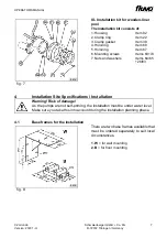
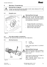
fig. 23
L
Air hose
28
Non-return air valve
29
Air line hose tail
30
Hose tail
52
Air pipe clamp
56
Fixing bracket
Connect the non-return air valve (28) and
the air line hose tail (29) to the air hose
(L). Warm the air hose (L) up prior to
connecting. Fasten with the air pipe
clamp (52).
Fasten the non-return air valve with the
fixing bracket (56) to the pool wall or
similar. In the case of a ground level
overflow, place the non-return air valve in
the duct, see detail “B”.
Warning!
To position the non-return air valve also please observe the information under
chapter 4.2.
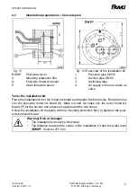
fig. 24
A
Hose coupling
B
Plug sleeve
D
Face plate assembly
21
Hose
Drain the pool water, if already filled, to
below the installation kit. Firmly place the
hose (21) with the hose coupling (A) onto
the plug sleeve (B) on the face plate
assembly (D). With that the air button is
connected to the switchgear cabinet.
8230
8231
15


