Installation and commissioning DATAEAGLE 3XXX Classic
Chapter 5
– Extension and exchange
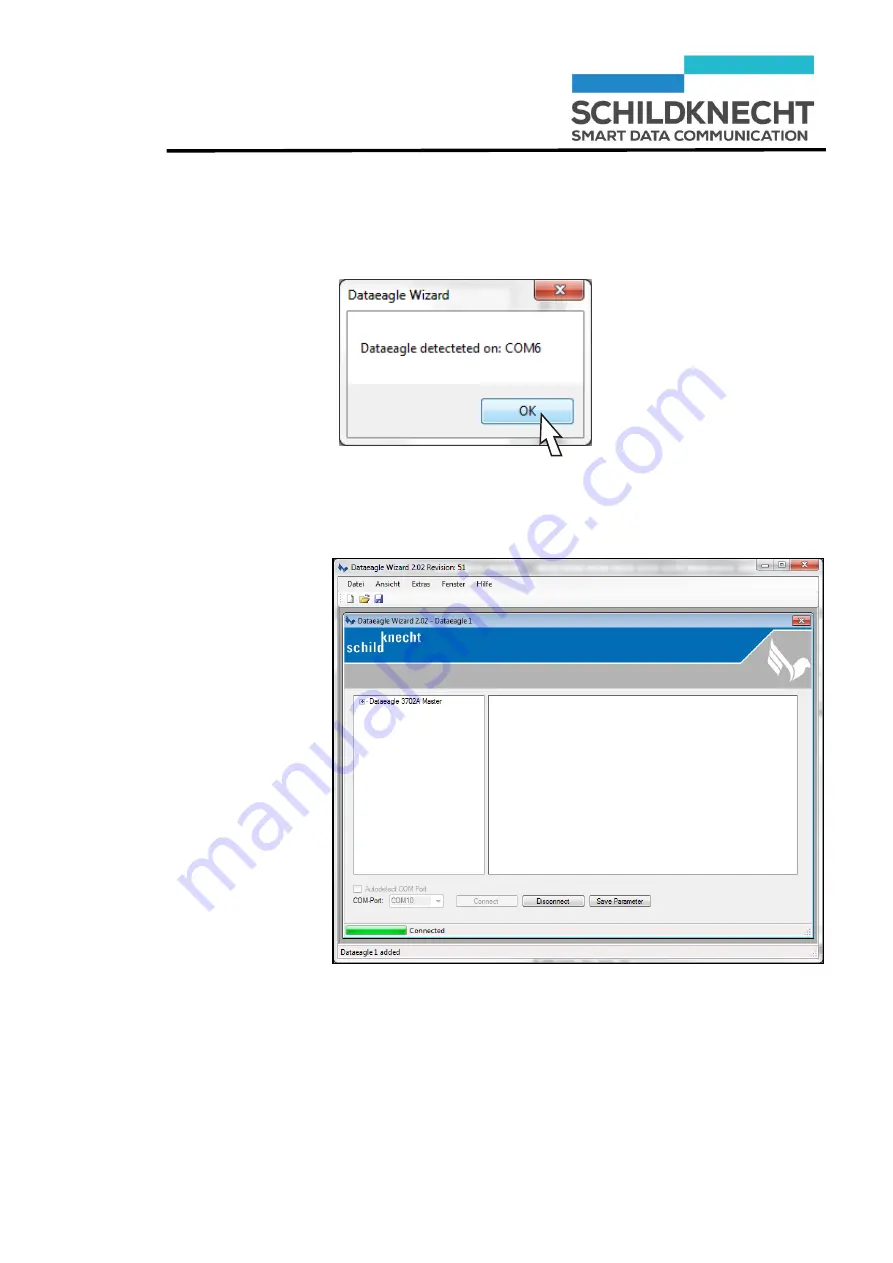
After the radio module is detected the following message appears:
Acknowledge with „OK“.
The Radio Master is shown, e.g. Dataeagle 3712A Master.
Страница 1: ...ual Wireless Data System DATAEAGLE 3XXX Classic Schildknecht AG D 71711 Murr Haugweg 26 Phone 49 0 7144 89718 0 Fax 49 0 7144 8971829 Email office schildknecht ag Internet www schildknecht ag DATAEAGLE 3XXX A Classic Version 06 07 2016 ...
Страница 2: ...operating instructions Warranty Schildknecht AG can accept no liability for indirect damage or direct damage incidental damage consequential damage or compensation for expenses incurred by performance of contract which arise from delivery provision and use of this material Introduction The technical description of the wireless data systems from Schildknecht AG consists of an operating instruction ...
Страница 3: ...ew important things to say about safety Please observe these instructions without fail in order to avoid property damage and personal injury We show you step by step how to install the system put it into operation and how to operate it Any questions First have a look in the table of contents You will quickly find what you are looking for If you do need us in person just call us or send a fax Schil...
Страница 4: ...stallation of new devices 4 4 4 1 Overview Installation 4 4 4 2 Install unit on top hat rail 4 5 4 3 Install antenna cable 4 6 4 4 Connect Profibus plug 4 7 4 5 Connect power supply 4 7 5 Extension and exchange 5 9 5 1 Preparation 5 9 5 1 1 System requirements 5 9 5 1 2 Create a new folder 5 9 5 1 3 Microsoft Internet Explorer 5 10 5 1 4 Install USB drivers 5 11 5 1 5 Install Dataeagle Wizard 5 15...
Страница 5: ...l values for the filter time 6 5 6 3 1 Default 6 5 6 3 2 Recommendation for operation 6 5 6 3 3 Recommendation for commissioning 6 5 6 3 4 Recommendation for applications with Profisafe 6 5 7 Working with the diagnostic slave 7 1 7 1 General information 7 1 7 2 Mode of operation 7 2 7 3 Integrate the diagnostic slave into a Profibus network 7 3 7 3 1 Integrate GSD file of diagnostic slave in Step ...
Страница 6: ...ollowed by a description about how the status of the system changes after an operation has been carried out 1 2 Copyright and brand names Brand names and product names mentioned in this manual are trademarks or registered trademarks of their respective owners Microsoft Windows 7 Windows Vista Windows 2000 Windows XP and Microsoft Internet Explorer are registered trademarks of Microsoft Corp Adobe ...
Страница 7: ... according safety instructions have to be observed under all circumstances Safety instructions which apply to all product families are described in the operating instructions for wireless data systems DATAEAGLE This manual is part of the system documentation Read these instructions before installation and commissioning of the wireless data system Safety instructions which apply only to an individu...
Страница 8: ...ng installation Static charges can damage electronic devices Remove electrostatic discharge from your body before touching the device The modules must not be opened or modified except the steps described in this manual Do not repair the module yourself replace it with an equivalent module Repairs may only be carried out by the Schildknecht AG The Schildknecht AG is not liable for damage resulting ...
Страница 9: ... the context of safety regulations qualified personnel are individuals authorized to commission to ground and to identify equipment and systems in accordance with the safety engineering standards All operating personnel must be trained accordingly Personnel involved with operating the unit in conjunction with controllers must possess sound programming skills for the individual controller and progr...
Страница 10: ...n The system is used for the wireless Profibus transmission It consists of a radio master and up to 4 radio slaves depending on the device type The DATAEAGLE can have up to 8 Profibus slaves depending on the device type The radio links work like a Profibus cable Each radio module is identified by its address ...
Страница 11: ... the software Dataeagle Wizard see chapter 5 3 8 New devices are pre configured in the factory Further settings are not necessary Type Radio technology Transmission power Profibus Profibus Slaves Radio Slaves 3712 2 4 GHz Bluetooth 100 mW bis 1 5 MBit max 8 max 4 3713 2 4 GHz Bluetooth 100 mW bis 1 5 MBit max 4 max 3 3715 2 4 GHz Bluetooth 100 mW bis 1 5 MBit max 4 max 1 3323 869 MHz 500 mW bis 1 ...
Страница 12: ...s Status LEDs n c Busfehler BF Status LEDs n c LINK Bedeutung der Status LEDs Name Farbe Funktion BF Rot Profibusstatus Dataeagle Master beim Slave immer aus Statisch an keine Verbindung zum Profibus Master bzw Baudrate zu hoch Blinkend Fehler irgendeiner der angeschlossenen DP Teilnehmer ist nicht im Datenaustausch Aus alle angeschlossenen DP Teilnehmer befinden sich im Datenaustausch LINK Blau D...
Страница 13: ...edure Thereby you avoid electromagnetic interferences and you improve the data transmission quality New devices are pre configured in the factory Further settings are not necessary 4 1 Overview Installation The installation is very easy and is carried out according to the procedure shown below Install unit on top hat rail Connect antenna cable Connect Profibus plug Connect power supply In case of ...
Страница 14: ...ation and commissioning DATAEAGLE 3XXX Classic Chapter 4 Installation of new devices 4 2 Install unit on top hat rail Place the unit diagonally from above on the top hat rail Press the unit strongly downwards ...
Страница 15: ...ble Connect the antenna cable to the antenna connection of the radio module The radio module may be damaged if the antenna cable is fastened too tight Connect the antenna cable only hand tight Install the antenna at the designated place Observe the guidelines for an optimum antenna installation in chapter 7 Tips and Tricks ...
Страница 16: ...er 4 Installation of new devices 4 4 Connect Profibus plug Connect the Profibus plug 4 5 Connect power supply Connect the power supply according to the diagram shown below Either the 24 V supply of the control cabinet or of the Profibus Master Slave can be used ...
Страница 17: ...tage of 24 V DC falls into the category SELV safety extra low voltage and is thereby no subject to the EC low voltage directive Usage of other power supplies is not allowed For connection to the 230 V AC mains supply an external wall power supply with 12 24 V DC 1 A output voltage can be used A self healing 0 7A fuse is integrated into the input circuit This fuse cannot be exchanged The device has...
Страница 18: ...ard must be installed on your PC and the radio module has to be connected to the PC Do not yet connect the USB cable to the PC 5 1 Preparation 5 1 1 System requirements You need a PC with Operating system Windows 7 Vista XP oder 2000 Microsoft Internet Explorer Acrobat Reader Decompression program WinRAR WinZIP or similar One free USB interface 5 1 2 Create a new folder Create a new folder e g Dat...
Страница 19: ...xplorer To ensure a safe function it is important that you define Microsoft Windows Explorer as standard browser before you insert the CD ROM into the drive Only when Microsoft Internet Explorer is not the standard browser Call the internet options via control panel Define the Internet Explorer as standard browser ...
Страница 20: ...nstall USB drivers For data transmission between PC and radio module it is necessary to install the USB drivers Insert the CD in your CD ROM drive The browser shows the available documents and downloads for all Schildknecht products Scroll until you find your product e g DATAEAGLE 3712 Click on ...
Страница 21: ...hange The available files applications are shown Start the application CDM v2 12 00 WHQL Certified Double click The following message appears Click on Alle extrahieren Mark the application CDM v2 12 00 WHQL Certified with the right mouse key Execute the application as administrator ...
Страница 22: ...Installation and commissioning DATAEAGLE 3XXX Classic Chapter 5 Extension and exchange Click on Extract The installation wizard is started Click on Weiter The license agreement is shown ...
Страница 23: ...ssic Chapter 5 Extension and exchange Click on Weiter The USB drivers are loaded Click on Fertig stellen The USB drivers are now installed Use the Auto detect COM Port function of the Dataeagle Wizard to establish a USB connection to the radio module ...
Страница 24: ...rd You may load the Dataeagle Wizard either from the CD or from the homepage Load Dataeagle Wizard from the CD Select your product in the browser e g DATAEAGLE 3713 Click on Load Dataeagle Wizard from the homepage http www schildknecht ag download konfiguration und diagnosesoftware Start download Open an unpack file ...
Страница 25: ...Installation and commissioning DATAEAGLE 3XXX Classic Chapter 5 Extension and exchange Start Setup The installation program is started Click on Install The program is loaded and started ...
Страница 26: ...ditional Profibus Slave to existing or new Radio Slave Check if the Profibus slave addresses must be assigned manually see chapter 5 4 5 2 2 Additional Radio Slave The extension with additional Radio Slaves is carried out according to the procedure shown below Install radio module on top hat rail Connect antenna cable Connect Profibus plug Connect power supply Start Dataeagle Wizard Configure Radi...
Страница 27: ...sioning DATAEAGLE 3XXX Classic Chapter 5 Extension and exchange 5 2 3 Start Dataeagle Wizard Start the Dataeagle Wizard The Dataeagle Wizard is stored in the folder Schildknecht AG during installation The start screen appears ...
Страница 28: ...Installation and commissioning DATAEAGLE 3XXX Classic Chapter 5 Extension and exchange 5 2 4 Configure Radio Master Connect the Radio Master with an USB cable to the PC Click on Connect ...
Страница 29: ...n and commissioning DATAEAGLE 3XXX Classic Chapter 5 Extension and exchange After the radio module is detected the following message appears Acknowledge with OK The Radio Master is shown e g Dataeagle 3712A Master ...
Страница 30: ...ouble click on the device name then double click on Radio The radio module addresses are shown In this example the radio system consists of one Radio Master with address 01 and two Radio Slaves with the addresses 02 and 03 The address of the newly added Radio Slave must now be entered into the Radio Master ...
Страница 31: ...Installation and commissioning DATAEAGLE 3XXX Classic Add new address The new Radio Slave address is shown Chapter 5 Extension and exchange Click on Add Enter the new address e g 4 and click OK ...
Страница 32: ...EAGLE 332X or once on Bluetooth for DATAEAGLE 37XX The set channel or the Bluetooth MAC address is shown Note the channel e g Channel 1 or the Bluetooth MAC address e g 0012f30e69d5 Check if the Profibus slave addresses must be assigned manually see chapter 5 4 Click on Save Parameter The new configuration of the Radio Master is saved Click on Disconnect ...
Страница 33: ...ning DATAEAGLE 3XXX Classic Chapter 5 Extension and exchange 5 2 5 Configure Radio Slave Connect the Radio Slave with an USB cable to the PC Click on Connect Acknowledge with OK The Radio Slave is shown e g Dataeagle 3712A Slave ...
Страница 34: ... on Radio The radio module addresses are shown Enter the correct addresses The Radio Master has the station address 01 and partner address 04 was assigned to the new radio module Therefore you have to enter Station address 04 and Partner address 01 Of course you may assign other Station and Partner addresses The addresses must only correspond to each other ...
Страница 35: ...Click once on 869 MHz for DATAEAGLE 332X or once on Bluetooth for DATAEAGLE 37XX The channel or the Bluetooth MAC address is shown Enter the channel or the Bluetooth MAC address you have noted before Click on Save Parameter The new configuration of the Radio Slave is saved Click on Disconnect The configuration is finished ...
Страница 36: ...dule is carried out according to the procedure shown below Remove the wiring Remove the old module Install unit on top hat rail Connect antenna cable Connect power supply Start Dataeagle Wizard and configure module Please read first the information about Profibus Slave in chapter 5 4 before you de install a Radio Master ...
Страница 37: ...nsion and exchange 5 3 1 Remove wiring Remove the Profibus plug and the antenna cable Remove the power supply best with a small screw driver 5 3 2 Remove old module Pull the foot catch downwards and tilt the module upwards 5 3 3 Install new module See chapter 4 2 to 4 5 ...
Страница 38: ...ion and exchange 5 3 4 Start Dataeagle Wizard No configuration with the Dataeagle Wizard is necessary when an I O module has been exchanged Start the Dataeagle Wizard The Dataeagle Wizard is stored in the folder Schildknecht AG during installation The start screen appears ...
Страница 39: ... on the type of the radio module DATAEAGLE 332X with 869 MHz or DATAEAGLE 37XX Bluetooth and whether a Radio Master or a Radio Slave have been exchanged For a better understanding we use the configuration below and use two examples to explain the exchange Example 1 Radio Slave 2 with address 03 is exchanged Example 2 Radio Master 2 with address 01 is exchanged ...
Страница 40: ...ample 1 Exchange of a Radio Slave Connect Radio Master to Wizard Read off Radio Master address Determine address of the exchanged Radio Slave Connect Radio Slave to Wizard Enter Radio Master and Radio Slave address Enter channel or Bluetooth MAC Address Test configure Profibus Slave Connect the Radio Master with the USB cable to the PC ...
Страница 41: ...missioning DATAEAGLE 3XXX Classic Chapter 5 Extension and exchange Click on Connect After the radio module is detected the following message appears Acknowledge with OK The Radio Master is shown e g Dataeagle 3712A Master ...
Страница 42: ...aster with address 01 and three Radio Slaves with the addresses 02 03 and 04 Note the address of the Radio Master and the address of the exchanged Radio Slave If you do not know which Radio Slave has been exchanged you have to read off the station addresses of all unchanged Radio Slaves by using the Dataeagle Wizard Compare these addresses to the partner addresses in the Radio Master The address w...
Страница 43: ...ension and exchange Click once on 869 MHz for DATAEAGLE 332X or on Bluetooth for DATAEAGLE 37XX The set channel or the Bluetooth MAC address is shown Note the channel e g Channel 1 or the Bluetooth MAC address e g 0012f30e69d5 Check if the Profibus slave addresses must be assigned manually see chapter 5 4 ...
Страница 44: ...DATAEAGLE 3XXX Classic Configure Radio Slave Chapter 5 Extension and exchange Connect the newly installed Radio Slave with an USB cable to the PC Click on Connect Acknowledge with OK The Radio Slave is shown e g Dataeagle 3712A Slave ...
Страница 45: ...k on Radio The radio module addresses are shown Enter the correct addresses The Radio Master has the station address 01 and the exchanged radio module has the partner address 03 Therefore you have to enter Station address 03 and Partner address 01 Of course you may assign other Station and Partner addresses The addresses must only correspond to each other ...
Страница 46: ...Click once on 869 MHz for DATAEAGLE 332X or once on Bluetooth for DATAEAGLE 37XX The channel or the Bluetooth MAC address is shown Enter the channel or the Bluetooth MAC address you have noted before Click on Save Parameter The new configuration of the Radio Slave is saved Click on Disconnect The configuration is finished ...
Страница 47: ...ge of DATAEAGLE 332X 869 MHz Exchange of DATAEAGLE 37XX Bluetooth Read off channel Connect Radio Master to Wizard Connect Radio Master to Wizard Enter Radio Master and all Radio Slave address Enter Radio Master and all Radio Slave address Read off Bluetooth MAC Address Enter channel Test configure Profibus Slave Test configure Profibus Slave Connect Radio Slaves to Wizard Enter Bluetooth MAC Addre...
Страница 48: ...Installation and commissioning DATAEAGLE 3XXX Classic Connect Radio Slave to Wizard Chapter 5 Extension and exchange Connect the Radio Slave with the USB cable to the PC Click on Connect ...
Страница 49: ...on and commissioning DATAEAGLE 3XXX Classic Chapter 5 Extension and exchange After the radio module is detected the following message appears Acknowledge with OK The Radio Slave is shown e g Dataeagle 3712A Slave ...
Страница 50: ...hown e g The Radio Slave has station address 02 The partner address is 01 station of the Radio Masters Note station and partner address If you do not know the station addresses of all further Radios Slaves you have to read them off by using the Dataeagle Wizard and note them as well The further procedure depends on the type of the radio module DATAEAGLE 332X with 869 MHz or DATAEAGLE 37XX Bluetoot...
Страница 51: ...ning DATAEAGLE 3XXX Classic Display channel Chapter 5 Extension and exchange Procedure for exchanging a Radio Master type DATAEAGLE 332X with 869 MHz Click once on 869 MHz The set channel is shown Note the channel e g Channel 1 ...
Страница 52: ...TAEAGLE 3XXX Classic Configure Radio Master Chapter 5 Extension and exchange Connect the newly installed Radio Master with an USB cable to the PC Click on Connect Acknowledge with OK The Radio Master is shown e g Dataeagle 3712A Master ...
Страница 53: ...e shown Enter now the correct addresses In this example the radio system consists of one Radio Master with address 01 and three Radio Slaves with the addresses 02 03 and 04 Therefore station address 01 and partner addresses 02 03 and 04 must be entered The station address can be entered directly Place the cursor into the address field and enter the address Partner addresses can only be entered by ...
Страница 54: ...oning DATAEAGLE 3XXX Classic Add partner address Station and all partner addresses are displayed Chapter 5 Extension and exchange Click on Add Enter the first address e g 02 and click OK Repeat the entry for the other addresses ...
Страница 55: ... once on 869 MHz The channel as pre set in the factory is shown Enter the channel you have noted before Check if the Profibus slave addresses must be assigned manually see chapter 5 4 Click on Save Parameter The new configuration of the Radio Slave is saved Click on Disconnect The configuration is finished ...
Страница 56: ...aster Chapter 5 Extension and exchange Procedure for exchanging a Radio Master type DATAEAGLE 37XX with Bluetooth Connect the newly installed Radio Master with an USB cable to the PC Click on Connect Acknowledge with OK The Radio Master is shown e g Dataeagle 3712A Master ...
Страница 57: ...are shown Enter the correct addresses In this example the radio system consists of one Radio Master with address 01 and three Radio Slaves with the addresses 02 03 and 04 Therefore station address 01 and partner addresses 02 03 and 04 must be entered The station address can be entered directly Place the cursor into the address field and enter the address Partner addresses can only be entered by us...
Страница 58: ...oning DATAEAGLE 3XXX Classic Add partner address Station and all partner addresses are displayed Chapter 5 Extension and exchange Click on Add Enter the first address e g 02 and click OK Repeat the entry for the other addresses ...
Страница 59: ...The Bluetooth MAC Address of the newly installed Radio Master is shown Note the Bluetooth MAC address e g 0012f30e69d5 Check if the Profibus slave addresses must be assigned manually see chapter 5 4 Click on Save Parameter The new configuration of the Radio Slave is saved Click on Disconnect The configuration of the Radio Master is finished ...
Страница 60: ... Click on Connect Acknowledge with OK The Radio Slave is shown e g Dataeagle 3712A Slave Click once on Bluetooth The Bluetooth MAC Address is shown Enter the Bluetooth MAC address you have noted before Click on Save Parameter The new configuration of the Radio Slave is saved Click on Disconnect Repeat these steps for all other Radio Slaves The configuration is finished ...
Страница 61: ...irmware version can be found on the type label of the radio module If radio modules with an older firmware version are used in the radio system or if Profibus Slave Addresses have been assigned manually in the Dataeagle Wizard then Profibus Slave Addresses must be assigned when a new Profibus slave is added to the radio system to an existing or new Radio Slave or when the Radio Master is exchanged...
Страница 62: ...eps depend on your knowledge about the radio system Case 1 You know that the Profibus Slaves in the radio system are detected automatically or you know that Profibus Slave Addresses have been assigned and you know these addresses Continue with the de installation of the Radio Master chapter 5 3 1 Case 2 You know that Profibus Slave Addresses have been assigned and you don t know these addresses or...
Страница 63: ...es Chapter 5 Extension and exchange If the described steps don t work the Radio Master is defect in a way that you cannot read off the Profibus Slave Addresses Abort the procedure and continue with Check radio modules Connect the Radio Master with an USB cable to the PC Click on Connect ...
Страница 64: ...n and commissioning DATAEAGLE 3XXX Classic Chapter 5 Extension and exchange After the radio module is detected the following message appears Acknowledge with OK The Radio Master is shown e g Dataeagle 3712A Master ...
Страница 65: ...us Slave Addresses assigned the screen shows No DP Slave configured No Profibus Slave Addresses must be assigned in the new Radio Master Continue with the de installation of the Radio Master chapter 5 3 1 Profibus Slave Addresses assigned Note Profibus Slave Addresses Then continue with the de installation of the Radio Master chapter 5 3 1 No address assigned Profibus Slave addresses ...
Страница 66: ...32_M83 or DE32_S83 If one of the radio modules in the system has an older firmware version e g DE32_M82 or lower you must assign Profibus Slave Addresses in the new Radio Master If all radio modules in the system have a newer firmware version e g DE32_M83 or higher you must not assign Profibus Slave Addresses in the new Radio Master They are detected automatically Continue with de installation of ...
Страница 67: ...the following steps when a new Profibus Slave has been connected to an existing or a new Radio Slave Double click on the Interface then once on DP Parameter No Profibus Slave Addresses assigned the screen shows No DP Slave configured Profibus Slaves are detected automatically Continue with chapter 5 2 5 No address assigned Address assigned in Wizard ...
Страница 68: ...tion and commissioning DATAEAGLE 3XXX Classic Profibus Slave Address assigned Chapter 5 Extension and exchange Click on Add DP Slave Enter the new address and click on OK The new Profibus Slave Address is shown ...
Страница 69: ... on DP Parameter The factory setting is shown Before de installation of the Radio Master you have checked if Profibus Slave Addresses have been assigned or if they are detected automatically If they are detected automatically no further steps are required here Continue with the configuration of the Radio Master If Profibus Slave Addresses have been assigned in the old Radio Master you must now ent...
Страница 70: ...Address Chapter 5 Extension and exchange Click on Add DP Slave Enter the new address and click on OK The new Profibus Slave Address is shown Repeat this procedure for all Profibus Slaves in the radio system Afterwards you can continue with the configuration of the Radio Master ...
Страница 71: ...adio slave cannot be accessed due to an interference a bus error is indicated to the Profibus master only after the filter time has been elapsed Only then are the outputs of the connected DP slaves switched into safe condition The advantage is that Profibus bus errors can be supressed for an adjustable time and thus the system availability van ib increased 6 2 Setting of the filter time Connect th...
Страница 72: ...Installation and commissioning DATAEAGLE 3XXX Classic Chapter 6 Filter time Click on Connect After the radio module has been found the following message appears Acknowledge with OK ...
Страница 73: ...TAEAGLE 3XXX Classic Adjustment range for the filter time 0 1s to 25 5s Chapter 6 Filter time The Radio Master is shown e g Dataeagle 3712A Master Double click on the device name then double click on Interface then once on DP Parameter ...
Страница 74: ...Installation and commissioning DATAEAGLE 3XXX Classic Chapter 6 Filter time Click on Save Parameter The new configuration is saved Click on Disconnect No adjustments are necessary at the Radio Slave ...
Страница 75: ...e to disturbance afflicted environment 6 3 3 Recommendation for commissioning For commissioning it is recommended to select a value between 1 s and 4 s This eliminates an early triggering of the filter Afterwards the filter time may be reduced 6 3 4 Recommendation for applications with Profisafe In applications with Profisafe the filter time should be set higher than the SIL monitor time at Profis...
Страница 76: ...etwork The provided GSD file DE3002_D GSD can be used to integrate the diagnostic slave into the Profibus network The diagnostic data is separated into 8 blocks of data Each block has a size of 32 Byte The following diagnostic data is provided by the DATAEAGLE Block 0 General diagnostic data Block 1 Slave addresses Block 2 Status of Profibus connection to the individual DP slaves Block 3 Response ...
Страница 77: ... Diagnostic slave 7 2 Mode of operation The illustration shows the mode of operation in principle Step 1 The PLC addresses the diagnostic slave and selects a data block Step 2 The diagnostic slave provides the selected data block Step 3 The PLC reads the data block ...
Страница 78: ...for Simatic controllers Please contact your controller supplier when you use another controller 7 3 1 Integrate GSD file of diagnostic slave in Step 7 First the provided GSD file has to be integrated into Step 7 Proceed with the following steps Insert the CD into your CD ROM drive The browser shows the available documents and downloads for all Schildknecht products ...
Страница 79: ...TAEAGLE 3712 Click on The installed decompression program is started and the available files are shown Unpack the files into the previously created folder see chapter 5 1 2 Copy the files DE3002_D GSD and DE3002_D BMP into the directory STEP7 S7TMP Open the Hardware configuration Select Install GSD files in the menu Extras ...
Страница 80: ... slave in the hardware catalogue under Profibus DP Weitere Feldgeräte Allgemein DE3002 Diagnose Integrate the diagnostic slave into the Profibus network and assign the Profibus address Download the hardware configuration into the DP master Start the Dataeagle Wizard The Dataeagle Wizard is stored in the folder Schildknecht AG during installation ...
Страница 81: ...Installation and commissioning DATAEAGLE 3XXX Classic Chapter 7 Diagnostic slave The start screen appears Connect the Radio Master with an USB cable to the PC ...
Страница 82: ...Installation and commissioning DATAEAGLE 3XXX Classic Chapter 7 Diagnostic slave Click on Connect After the radio module is detected the following message appears Acknowledge with OK ...
Страница 83: ...Installation and commissioning DATAEAGLE 3XXX Classic Chapter 7 Diagnostic slave The Radio Master is shown Double click on the device name then double click on Interface then once on DP Parameter ...
Страница 84: ...Installation and commissioning DATAEAGLE 3XXX Classic Chapter 7 Diagnostic slave Click on Add Diagnoseslave Enter the Profibus address of the diagnostic slave and click OK ...
Страница 85: ...n MW0 CALL DPRD_DAT LADDR w 16 100 RET_VAL MW0 RECORD P DB100 DBX 0 0 BYTE 32 Example Send data from DB101 starting from DBB0 to the diagnostic slave The memory address of the diagnostic slave see hardware configuration is 256 100hex The error code will be saved in MW2 CALL DPWR_DAT LADDR w 16 100 RECORD P DB101 DBX 0 0 BYTE 32 RET_VAL MW2 Controlling the diagnostic slave The byte 0 of the transmi...
Страница 86: ...lave Position Meaning Value Byte 0 Access display page 0 7 or 0 255 2 0 to 255 Byte 1 Controller Bit 0 1 resets the counters Additional parameters depending display page 0 without function 1 reset or 0 255 Byte 2 bis 30 Parameter depending on the display page 0 255 Byte 31 Reserved 0 Receiving data from diagnostic slave Diagnostic data ...
Страница 87: ...onded from the slaves Byte 6 7 Quantity of slave failures Sum of all interrupted connections from the transmitter side DATAEAGLE master reports bus error Byte 8 9 Sum of all slave responding telegrams Byte 10 13 DATAEAGLE device type ASCII coded e g 3002 Byte 14 17 DATAEAGLE Software version ASCII coded e g 9 75 Byte 18 21 Software Profibus interface ASCII coded e g V 42 Byte 22 Radio channel Set ...
Страница 88: ... 0 10 5 DataExchange Byte 31 2 Feedback from display side here 2 The Status the internal state machine allows the diagnosis of the internal Profibus interface Under normal conditions it shows 5 If no communication with the slaves can be established e g because the connected slaves are not compatible you may run a remote diagnosis Block 3 Response time of the slaves Data exchange time Position Mean...
Страница 89: ...er of restarts due to errors Initialisation counter Position Meaning Value Control Value Byte 0 Number of restarts slave 1 transmission side 0 to 255 Display number here 5 Byte 1 Number of restarts slave 2 transmission side 0 to 255 0 no function 1 reset counter Byte 2 Number of restarts slave 3 transmission side 0 to 255 Byte 31 5 Feedback from display side here 5 Block 6 Number of restarts from ...
Страница 90: ... automatic mode 255 radio slave 1 off Byte 2 Radio address of slave2 0 to 99 127 slave not present 0 no function 1 automatic mode 255 radio slave 1 off Byte 30 Radio address of slave30 0 to 99 127 slave not present 0 no function 1 automatic mode 255 radio slave 30 off Byte 31 8 Feedback from display side here 8 DATAEAGLE 3xxx A Master tries to connect cyclic all radio slaves which he knows through...
Страница 91: ...of slave1 0 to 255 0 no function 1 reset counter Byte 2 Radio retry of slave2 0 to 255 Byte 30 Radio retry of slave30 0 to 255 Byte 31 9 Feedback from display side here 9 Block 10 Display of the maximum timeout radio slaves Position Meaning Value Control Value Byte 0 Dummy 0 Display page here 10 Byte 1 Max Timeout Radio slave 1 0 to 255 sec 0 no function 1 reset counter Byte 2 Max Timeout Radio sl...
Страница 92: ...EAGLE 3XXX Classic Chapter 7 Diagnostic slave If you read cyclic this pages and switch between them you have to read Byte 31 to be sure that the delivered page is the requested one There could some PLC cycles between request and delivery ...
Страница 93: ...sion path in your application This way you can reduce Profibus bus errors at the PLC with a high filter time By monitoring the initializing counter you can detect even the smallest radio interruptions before they are recognized by the system as a Profibus error For optimization use the data from Block 5 Application 3 Problems during commissioning Sometimes it occurs that the transmission path does...
Страница 94: ...ing and disposal Remove the Profibus plug and the antenna cable Remove the power supply best with a small screw driver Pull the module downwards and tilt the module upwards Dispose the devices correctly Observe the applicable local waste disposal regulations and legislation when disposing the devices ...
Страница 95: ...e devices for achieving a higher interference resistance and surge immunity will become partly inefficient The interference resistance of the complete system depends highly on the correct installation place of installation and wiring Before installation always check which installation instructions are required by the supplier of the controller for a safe operation These instructions should be cons...
Страница 96: ...MC grounding in general PE Place the bus cables at least 20 cm away from the power cables if possible in separate cable ducts Connect all unused leads of a cable always on both sides to PE Use metallic or metallised plug housing The shielding of the cable should always be connected to the plug housing Always mount all electronic devices on a galvanized mounting plate in the control cabinet This mo...
Страница 97: ...ual system components star shaped towards the potential equalization rail Thereby you avoid that interferences are injected by PE loops which act as antennas Unfavourable earth protection connections and loops may bridge EMC measurements and will make them inefficiently Pay unconditional attention to a separation of N neutral conductor and PE earth protection inside the control cabinet Measure wit...
Страница 98: ...earth is required If a circular current across the screen is measured measure with a clamp on ammeter a DC isolation should be realized by using a X capacitor 100nF 230V The capacitor acts with low impedance against high frequent interferences but avoids circular currents In this installation the mounting plate may not be grounded through PE Fig 5 2 PE free installation Legend Geschirmte Profibusl...
Страница 99: ...iation Chapter 9 Tips and Tricks 9 2 Guidelines for optimized installation of antennas All antennas should have the same orientation e g vertical So nicht Keep sufficient distance to metal parts and walls Keep maximum distance to motors and frequency converters Provide free radiation Max ...
Страница 100: ...ips and Tricks The best data transmission quality will be achieved when the antennas are installed in a line of sight at an elevated and free location Install antennas outside of the control cabinet Electromagnetic radiation Keep at least a distance of 20 cm to the antennas when the devices are in operation ...
Страница 101: ...d radio station and radio partner address Check the distance towards the partner station Select first a distance of a few meters and increase the distance step by step up to the intended distance Check the antenna connection Check if all antennas are connected correctly Pay attention that coax antenna cable is not flexed Check next if all antennas are installed according to the guidelines describe...
Страница 102: ...ure range 20 C 60 C 20 C 60 C Conformity CE FCC CE FCC Weight 650 g 650 g Width 233 mm 233 mm Height 106 mm 106 mm Depth 39 mm 39 mm Colour black black Radio technology Frequency 2 4 GHz Bluetooth 2 4 GHz Bluetooth Transmitting power 100mW 100mW Max number of radio slaves 4 St 4 St Typical indoor range 100 m 100 m Typical outdoor range 300m 300m Antenna connection SMA connector 50 Ohm SMA connecto...
Страница 103: ...range 20 C 60 C 20 C 60 C Conformity CE FCC CE Weight 650 g 800 g Width 233 mm 233 mm Height 106 mm 106 mm Depth 39 mm 39 mm Colour black black Radio technology Frequency 2 4 GHz Bluetooth 869 MHz Transmitting power 100mW 500mW Max number of radio slaves 1 St 3 St Typical indoor range 100 m 300 m Typical outdoor range 300m 1 3 km Antenna connection SMA connector 50 Ohm SMA connector 50 Ohm INTERFA...