background image

Disassembly

Removing the Optical (CD/DVD) Device 2 - 11

2.Disassembly

6.

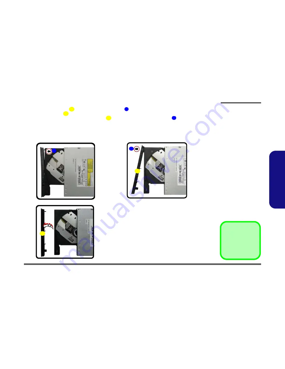
Carefully pry the bezel 

 off the optical device at point 

 (

Figure 7d

)

.

7.

Separate the bezel 

 and the optical device.

8.

Reverse the process to attach the front bezel 

 with the new optical device at point 

 (

Figure 7f

).

9.

Insert the new device and carefully slide it into the computer (the device only fits one way. DO NOT FORCE IT; The 
screw holes should line up).

10. Replace the component bay cover and tighten the screws.
11. Restart the computer to allow it to automatically detect the new device.

8

7

8

8

9

8. Bezel Cover

1  Screw

f.

8

d.

e.

7

8

9

Figure 7

Optical Device 

Removal (cont’d.)

d. Pry the bezel off the opti-

cal device.

e. Separate the bezel and

optical device

f. Install the front bezel.

Содержание W703

Страница 1: ......

Страница 2: ...down properly and don t forget to save your work Remember to periodically save your data as data may be lost if the battery is depleted Do not expose the computer to any shock or vibration Do not plac...

Страница 3: ...e sure to disconnect it by the plug head not by its wire Make sure the socket and any extension cord s you use can support the total current load of all the connected devices Before cleaning the compu...

Страница 4: ...r hands or metal objects Battery Guidelines The following can also apply to any backup batteries you may have If you do not use the battery for an extended period then remove the battery from the comp...

Страница 5: ...ert the battery and tighten the screws 4 Securely attach any peripherals you want to use with the computer e g keyboard and mouse to their ports 5 Attach the AC DC adapter to the DC In jack at the rea...

Страница 6: ...sor Memory Expandable up to 16GB 32GB Note Four SO DIMMs are only supported by Quad Core CPUs Dual Core CPUs support two SO DIMMs maximum Core Logic Intel HM87 Express Chipset Security Security Kensin...

Страница 7: ...Mini IEEE1394a Port One RJ 45 LAN Jack One DC In Jack Note External 7 1CH Audio Output Supported by Head phone Microphone Line In and S PDIF Out Jacks Communication Built In Gigabit Ethernet LAN 2 0M...

Страница 8: ...t In PC Camera 2 PC Camera LED 3 Built In Microphone 4 LCD 5 Speakers 6 LED Indicators 7 Power Button 8 Illuminated Keyboard 9 TouchPad and Buttons 10 Fingerprint Reader Optional 3 2 1 8 9 7 6 5 4 5 N...

Страница 9: ...uction External Locator Front Right side Views Figure 2 Front Views 1 LED Power Indicators Figure 3 Right Side Views 1 Optical Device Drive Bay 2 Emergency Eject Hole 3 Headphone Jack 4 Microphone Jac...

Страница 10: ...e 4 Left Side View 1 Mini IEEE 1394a Port 2 RJ 45 LAN Jack 3 USB 3 0 Port USB Charge 4 USB 3 0 Port 5 Combined eSATA Powered USB 3 0 Port 6 Multi in 1 Card Reader 1 2 4 5 6 3 Figure 5 Rear View 1 Vent...

Страница 11: ...om View Figure 6 Bottom View 1 Sub Woofer 2 Fan Outlet Intake 3 Component Bay Cover 4 Primary HDD Bay 5 Secondary HDD Bay 6 Battery Overheating To prevent your com puter from overheating make sure not...

Страница 12: ...ing the connection make sure the connector is oriented in the same way The pin1 side is usually not indicated Pressure sockets for multi wire connectors To release this connector type grasp it at its...

Страница 13: ...not pull on the wire 6 Peripherals Turn off and detach any peripherals 7 Beware of static discharge ICs such as the CPU and main support chips are vulnerable to static electricity Before handling any...

Страница 14: ...ure 1a 3 Slide the latch in the direction of the arrow and hold it in place Figure 1a 4 The battery may be levered up at point Figure 1b 5 Lift the battery out of the compartment Figure 1c 4 Battery 1...

Страница 15: ...over and remove screws Figure 2a 3 Remove the hard disk bay cover by levering the cover at point Figure 2b Figure 2 HDD Assembly Removal a Locate the HDD bay cover and remove the screws b Remove the h...

Страница 16: ...rews and the insulation plate Figure 3e 7 Reverse the process to install a new hard disk do not forget to replace all the screws and covers 4 6 5 6 7 6 8 c d 5 6 4 7 e 8 5 HDD 8 HDD Insulation Plate 2...

Страница 17: ...following pages are all 9 5mm H hard disk drives In some cases 7mm H hard disk drives will be installed Figure 4 Foam Rubber Insert for 7mm H HDDs If you are replacing a 9 5mm H HDD with a 7mm H HDD...

Страница 18: ...Figure 5a 3 Remove the SSD shielding plate and remove the screw from the SSD Figure 5b 4 The SSD module will pop up and you can remove it from the computer Figure 5c 5 Reverse the process to install...

Страница 19: ...r and screw at point Figure 6b 4 Use a screwdriver to carefully push out the optical device out of the bay at point Figure 6d 5 Reverse the process to install any new optical CD DVD device Figure 6 Op...

Страница 20: ...7f 9 Insert the new device and carefully slide it into the computer the device only fits one way DO NOT FORCE IT The screw holes should line up 10 Replace the component bay cover and tighten the scre...

Страница 21: ...ws from the secondary HDD assembly Figure 8a 3 Slide the secondary HDD assembly in the direction of the arrow it will not move fully out of the bay Figure 8a 4 Lift the secondary HDD assembly up and o...

Страница 22: ...l the insulation plate 7 Slide the HDD assembly into the bay at an angle as illustrated 8 Make sure the insulation plate slides under the HDD bay guide at point 9 Slide the assembly in the direction o...

Страница 23: ...memory sockets are located under the keyboard not user upgradable If you are installing only two RAM modules then they should be installed in the primary memory sockets under the component bay cover N...

Страница 24: ...T FORCE the module it should fit without much pressure 11 Press the module in and down towards the mainboard until the slot levers click into place to secure the module 12 Replace the bay cover and sc...

Страница 25: ...ay cover page 2 14 2 Remove the top cover module Figure 12a 3 Remove screws Figure 12a 4 Carefully lift the keyboard up being careful not to bend the keyboard ribbon cable Figure 12c Figure 12 RAM Mod...

Страница 26: ...the slot as it will go DO NOT FORCE the module it should fit without much pressure 12 Press the module in and down towards the mainboard until the slot levers click into place to secure the module 13...

Страница 27: ...Carefully disconnect cables then remove screw from the module socket Figure 14b 4 The Wireless LAN module will pop up Figure 14c 5 Lift the Wireless LAN module Figure 14d up and off the computer Figur...

Страница 28: ...es covers each cable will have either a black or transparent cable cover are color coded for iden tification as outlined in the table below Cable 1 is usually connected to antenna 1 Main on the module...

Страница 29: ...over page 2 14 2 Locate the module it is visible at point Figure 15a 3 Carefully remove the screw from the module Figure 15b 4 Lift the module up and off the computer Figure 15b Figure 15 MSATA Module...

Отзывы: