11
2.Installation
2.5 Electric connections
Remote control panel mounting
The remote control panel has the following dimensions:
width 135 mm.
height 116 mm.
It can be flush mounted on any surface, providing the area behind is free of moisture and
condensation and there is enough depth to house the rear part of the panel (approx. 8 cm.).
To cut on the mounting surface will have the following dimensions:
width 115 mm.
height 97 mm.
Wiring
Power Supply
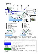
The Power supply, coming from the service batteries, needs to be connected to the ter
and – of the
Pump Box
. An automatic circuit breaker (16A for 12VDC systems and 10 A for
24VDC systems) must be installed on the power supply. The section of the cables must be
adequate. See the table below:
Voltage
Automatic
Cable lenght
switch
up to 3 mts
3 - 7 mt.
7-10 mt.
Volt
Ampere
mm2
AVG
mm2
AVG
mm2
AVG
12
16
4
11
10
7
16
5
24
10
2,5
13
4
11
4
11
Electric cables and switches selection table.
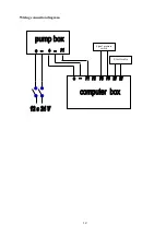
Connections between the pump box and the computer box
3 cables (section 2,5 mm2) will connect the pump box with the computer box.
The / - will provide the power to the computer box.
The cable P1 will provide the command to start the pump.
Connections between the computer box and pressure switch and electrovalve
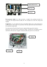
The pressure switch, positioned on the watermaker, has to be connected to the clamps PS/PS in
the computer box (section 2,5 mm2)
The electrovalve, positioned on the active carbon filter has to be connected to the clamps EV/EV
in the computer box (section 2,5 mm2)
Connection between the computer box and remote panel.
Connect the remote panel to the computer box using pre wired cable supplied (standard length 10
mts.)


