background image


Smoke extraction damper ERK-SO


TECHNICAL DOCUMENTATION


Service  |   

Construction subject to change 


No 

return 

possible 

      Version: 

2017-11-28 

Page 

39 

SERVICE


CHECKING THE FUNCTION, CLEANING, REPAIR 

Installation information 

The assembly must be made in a way that the inner viewing, 
cleaning and maintenance of the smoke damper is possible. To 
this end, suitable inspection openings must be provided in the 
connected smoke extraction ducts, if required. The connection 
to smoke extraction ducts made of wall boards is done accord-
ing to inspected duct-specific constructions. The connection to 
inspected sheet steel ducts or flexible connection pieces is 
done via the profiled mounting frame type PAR. 


Regulations for use and maintenance 

-  The operator of the smoke extraction installation must en-

sure that smoke extraction dampers are always kept in a 
ready-to-operate state and are maintained. 

-  Smoke extraction dampers must undergo maintenance at a 

six-month interval. If two consecutive inspections do not 
show any malfunctions, the maintenance interval of the 
smoke extraction dampers can be reduced to once a year. 

-  An inspection report must be produced, and the documents 

must be kept by the operator of the smoke extraction instal-
lation. 


o


The smoke extraction dampers must be installed in ac-
cordance with the technical documentation, installa-
tion, mounting and operating instructions. 

o


The work must be carried out by specialised compa-
nies only. 

o


Observe general accident prevention regulations. 

o


The smoke extraction dampers must be installed such 
that they are accessible. 

o


For internal inspection and cleaning of the smoke ex-
traction dampers, install inspection openings in the 
continuation connection lines. 

o


The cover of the temperature-resistant actuator hous-
ing can be dismounted for electrical wiring and must 
be properly remounted (screwed) once the wiring is 
completed; the actuator itself is maintenance-free. 

o


The electrical line installation must be at least E30, ac-
cording to DIN 4102-12. 

o


All electrical connections between actuator and power 
supply must be made according to the valid VDE guide-
lines. 

o


Observe the general guidelines for service according to 
DIN 31051 and EN 13306. 

o


For and after commissioning, the function of the entire 
smoke extraction system (interaction of all compo-
nents) must be regularly checked and documented in 
writing. 

o


The owner or operator must check whether the mini-
mum requirement for his operation is met. 

o


The function can be checked from the central unit. 

o


Repair work can be carried out only after consultation 
with the manufacturer.


1 - Inspection for commissioning on site 

o


Check the smoke extraction damper for damage. 

o


The smoke extraction damper must be installed in ac-
cordance with the technical documentation, installa-
tion, mounting and operating instructions. 

o


Dismount the cover of the temperature-resistant actu-
ator housing. 

o


The electrical wiring is done by a skilled electrician. Ca-
ble is inserted via a bore of exact fit = ø E90 or ø E30 
cable through the side wall of the temperature-re-
sistant actuator housing. 

o


Damper is in closed position, damper blade "CLOSED". 

o


Connection to electric circuit 

o


*Motors EK10 (SEL 1.90; 24 V AC/DC) / EK11 (SEL 2.90; 230 
V AC): 2-point activation of the smoke extraction damper. 

o


*Motors EK12 (SEL 1.90 SLC; 24 V AC/DC) / EK14 (EK12 
+ SPMa-1SR): activation via 2-wire connection (SLC sys-
tem) only in connection with communication device 
e.g. SPLM-4S 0SD Mod / SPMa-1SR (component of 
EK14). 

o


From the switch cabinet, give pulse for open position 
(smoke extraction) or closed position (fire). 

o


Damper blade moves to open/closed position; the 
movement is controlled by motor. 

o


Limit switches integrated in the actuator indicate the 
open/closed positions. 

o


Open / close running time < 60 sec. 

o


*Torque monitoring: SLC system at least 40 Nm. 

o


Screw the cover of the temperature-resistant actuator 
housing again. 


2 - Service for commissioning on site 

o


Remove / clean dirt / soiling detected during inspec-
tion. 


3 - Inspection after commissioning – every 6 months / once a 
year 

o


See Inspection for commissioning. 

o


Functional test of the smoke extraction damper on 
site. 

o


Functional test by external monitoring. 


4 - Service after commissioning depending on system equip-
ment and operating conditions 

o


Internal inspection 

o


Remove / clean system-specific dirt / soiling which af-
fects safety function. 
 

Measures to be implemented for service must be docu-
mented in writing and provide proof. 


5 - Repair 

o


Repair work must be carried out after consultation 
with the manufacturer.  

Содержание ERK-SO

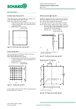
Страница 1: ...ng the necessary sup ply air within the smoke extraction installa tion For use in solid walls ceilings and smoke ex traction lines For automatic AA or manual MA triggering SPECIAL FEATURES Thermally i...

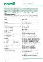
Страница 2: ...smoke extraction ducts 21 Connection options on or in horizontal smoke extraction ducts 21 Connection options on horizontal smoke extraction ducts in accordance with EN 12101 7 tested according to EN...

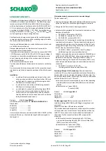
Страница 3: ...meframe 60 s or torque monitor ing For use in solid walls and ceilings for supplying air or ventilat ing smoke also in combination with smoke extraction lines in compliance with EN 121017 which have b...

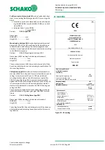
Страница 4: ...1 ERK SO housing consisting of 2 x 25 mm silicate structural panels 2 Profile connection frame PAR optional 3 Damper blade consisting of 3 x 20 mm silicate structural panels 4 Stop bar 40 x 20 mm with...

Страница 5: ...amper blade the lengths L standard are assigned to the heights H On request larger L dimensions are also possible Length L mm Other B or H dimensions 1 mm steps are available at an ex tra charge furth...

Страница 6: ...he inspection of the actuator by loosening the hexagon screws M6 x 100 mm H L a BS b MS 200 H 400 530 65 75 401 H 565 630 65 175 566 H 634 630 50 190 635 H 711 700 85 255 712 H 800 800 135 275 Detail...

Страница 7: ...t be provided for installation mor tar lining etc o Carry out a functional check of the smoke extraction damper before and after mounting and ensure ready access o Electrical installations or work on...

Страница 8: ...ay not be less than 100 mm When performing a mortar lining or direct installation make sure that the housing is not pressed toward the inside reinforcement If neces sary a statically active lintel mus...

Страница 9: ...des Gap 10 60 mm the dimensions of the threaded rods and the U steel can be found on pages 24 27 Suspension Detail B Mineral wool A1 melting point 1000 C gap 15 5 mm In the lower gap place only in cas...

Страница 10: ...additional accessory package is required for the connection to the smoke extraction dampers as a function of the dimension vertical position of the damper blade axle independent of the actuator positi...

Страница 11: ...ously MG II to III according to DIN 1053 or fire pro tection mortar of suit able grades Gap 10 60 mm U steel B vertical axle 1500 Mortar of category M2 5 to M15 according to EN 998 2 previously MG II...

Страница 12: ...I I II II II II III III III III III III III 225 I I I I I I I I I I I I I II II II II III III III III III III III 250 I I I I I I I I I I I I I II II II II III III III III III III III 275 I I I I I I...

Страница 13: ...I I I I II II II II II II II II II II II 325 I I I I I I I I I I I I I II II II II II II II II II II II 350 I I I I I I I I I I I I I II II II II II II II II II II II 375 I I I I I I I I I I I I I II...

Страница 14: ...le only o The distance to load bearing adjacent components wall solid ceiling is due to the construction at least 100 mm o Additional suspension required with U steel pole brace Wall opening Housing l...

Страница 15: ...f Insulfrax paper 50 x 5 mm thick Number and arrangement of mounting brackets WE S Proposed installation ERK SO in front of the concrete wall with suspension The brackets are fastened to the reinforce...

Страница 16: ...M8 M8 M8 M8 M8 M8 M10 M10 M10 M10 M10 M10 M10 M10 M10 M10 M12 M12 M12 M12 M12 M12 M12 500 M8 M8 M8 M8 M8 M10 M10 M10 M10 M10 M10 M10 M10 M10 M10 M10 M12 M12 M12 M12 M12 M12 M12 M14 550 M8 M8 M8 M10 M1...

Страница 17: ...en by the mortar manufac turer must be observed If the smoke extraction damper is installed during the construction of the ceiling the gaps s can be omitted The mortar bed depth must be executed in th...

Страница 18: ...0 mm Wet installation Mortar gap 10 60 mm Mortar of category M2 5 to M15 in ac cordance with EN 998 2 previously MG II to III according to DIN 1053 or fire protection mortar of suitable grades Mortar...

Страница 19: ...pax concrete Figure 12 Arrangement of WE S when installed in solid ceilings 200 225 250 275 300 325 350 375 400 450 500 550 600 650 700 750 800 900 1000 1100 1200 1300 1400 1500 200 2 2 2 2 2 2 2 2 2...

Страница 20: ...be at least 200 mm o The distance to load bearing adjacent components wall is due to the construction at least 100 mm Mounting information o Adjust connection between ERK SO and ceiling with water gla...

Страница 21: ...zontal smoke extraction duct 8 Smoke extraction ducts to EN 12101 7 tested to EN 1366 8 Min damper Optionally smoke extraction duct or finishing protective grating ASG E Smoke extraction duct to EN 12...

Страница 22: ...reinforcement in the smoke extraction duct The arrangement depends on the size of the ERK SO and the smoke extraction duct Detail B Detail A Circumferential fastening frame on site for connecting the...

Страница 23: ...g abP ETA etc Smoke extraction duct made of silicate struc tural panel in accordance with EN 12101 7 tested accord ing to EN 1366 8 Smoke extraction duct made of sheet steel in accordance with EN 121...

Страница 24: ...A 04 0026 for suspending the smoke extraction dampers M8 to M12 M16 and M20 Group of 2 Group of 4 Core bore diam eter is always 6 mm It is recommended to secure threaded rods screwed into the screw so...

Страница 25: ...er threaded rod N KP M6 0 18 20 1 120 6 12 29 M8 0 32 36 6 219 6 22 38 M10 0 50 58 0 348 0 35 47 M12 0 73 84 3 505 8 51 55 M14 0 97 115 0 690 0 70 33 M16 1 35 157 0 942 0 96 02 M20 2 08 245 0 1470 0 1...

Страница 26: ...ction Certified to EN 1366 1 Figure 20 Covered suspending brackets M12 Figure 21 Dimensions of the suspension covering Table 12 Suspension coverings Please note The weights of the suspension covering...

Страница 27: ...ng as shown opposite must be mounted Example of dimensioning Given ERK SO with the dimensions W 800 mm H 400 mm Suspension height 4 m The following weights must be added ERK SO according to table on p...

Страница 28: ...e in suspended ceilings shaft walls connected ventilation ducts etc if necessary They must be built in sufficient numbers and size and must not im pair the functioning of the smoke extraction dampers...

Страница 29: ...gram Correction table for octave weighting dB Oct fm Hz 63 125 250 500 1000 2000 4000 8000 KFO dB 4 2 0 1 4 9 15 21 Sound power per octave LW LWA KFO fm Hz 63 125 250 500 1000 2000 4000 8000 LW dB 37...

Страница 30: ...0 405 0 450 0 540 0 585 0 630 0 675 FQK 500 0 059 0 078 0 098 0 117 0 137 0 156 0 176 0 195 0 215 0 234 0 254 0 273 0 293 0 332 0 371 0 449 0 488 0 527 0 566 FQmin 0 701 0 610 0 542 0 475 0 429 0 418...

Страница 31: ...EK14 EK12 SPMa 1SR EK20 BE24 24 V AC DC EK21 BE230 230 V AC o Communication devices for actuator EK12 EK14 e g SPMa1SR part of EK14 or SPLM 4S 0SD Mod o Profile connection frame type PAR o Security gr...

Страница 32: ...VDE guidelines Technical data Table 14 Technical data of actuators Actuator type EK10 SEL 1 90 EK11 SEL 2 90 EK12 SEL 1 90 SLC EK14 EK12 SPMa 1SR Rated voltage V AC DC 24 AC 230 In connection with SP...

Страница 33: ...ction diagram for actuator type EK12 SEL 1 90 SLC 24 V AC DC EK14 EK12 SPMa 1SR 2 wire technology 2 strand see safety communication modules power line system SLC type SPMa 1SR or SPLM 4S 0SD Mod Cover...

Страница 34: ...side MS ASG2 or on both sides ASG3 o delivered loose 1 piece ASG4 2 pieces ASG5 Figure 26 Security grille type ASG E Recommendation Mounting of the ASG E in connection with the PAR with W or H 700 mm...

Страница 35: ...velocity relative to Astirn V m h l s Volumetric flow LWA dB A A weighted sound power level LW dB Sound power level octave LW LWA KFO B mm Width H mm Height L mm Length FQmin m Smallest flow cross se...

Страница 36: ...ernal impregnation 07 ACTUATOR EK10 SEL 1 90 24 V AC DC STANDARD ACTUATOR EK11 SEL 2 90 230 V AC EK12 SEL 1 90 SLC 24 V AC DC additional communication de vice required please order separately EK14 EK1...

Страница 37: ...EK10 24 V AC DC will be delivered Moreover the standard length will be assigned to the height H Alternative models or accessories at an extra charge Select as desired Housing and damper blade with ad...

Страница 38: ...ts made of steel 2 pieces are required for ERK SO The ceiling frame DR S is pressed circumferentially against ERK SO and solid ceiling and screwed to the ceiling If it is necessary due to the size the...

Страница 39: ...according to DIN 31051 and EN 13306 o For and after commissioning the function of the entire smoke extraction system interaction of all compo nents must be regularly checked and documented in writing...

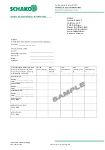
Страница 40: ...No Declaration of perfor mance no Series Actuator The following functional steps have been carried out according to the documents installation mounting and operating instructions before commissioning...

Страница 41: ...nfo schako de Web www schako de SAMPLE Functional test protocol for smoke extraction dampers Cons No ____________________ Defects found during the test on ________________________________________ Slug...

Страница 42: ...L 2343 Luxembourg A 1060 Wien PL 05 500 Piaseczno Phone 352 403 157 1 Phone 352 403 157 1 Phone 43 1 890 24 62 Phone 48 22 7263570 Fax 352 403 157 66 Fax 352 403 157 66 Fax 43 1 890 24 62 50 Fax 48 22...

Страница 43: ...to M12 24 Figure 20 Suspension fastenings M16 and M20 24 Figure 21 Covered suspending brackets M12 26 Figure 22 Dimensions of the suspension covering 26 Figure 23 Covered suspending brackets M14 to M...

Отзывы: