background image

32

BA 67

Schaeffler Technologies

Lubricators CONCEPT4

Replacing the cartridge

After replacing the cartridge, the depleted cartridge must be 
disposed of in accordance with the manufacturer's disposal 
instructions.

NOTICE

The empty level detection system counts the number of lubricant 
deliveries. If only a partially filled grease cartridge is used, the empty 
level detection system will fail and the lubrication point may become 
damaged. Only use a completely filled grease cartridge.

Ensure that the lubricator is supplied with voltage for reliable 
detection of the cartridge.

NOTICE

The upper housing part is preloaded. Risk of injury due to parts 
springing off when opening the upper housing part. Carefully loosen 
the collar ring and upper housing part.

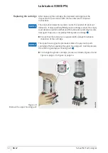
To change the grease cartridge, proceed as shown, 

Figure 20

 and 

Figure 6

, page 12 to 

Figure 8

, page 14.

Figure 20

Remove the upper housing part

0016E7A80016E7A8

Содержание CONCEPT4

Страница 1: ...Lubricators CONCEPT4 User manual...

Страница 2: ......

Страница 3: ...icants The lubricators contain highly efficient microprocessor controlled piston pumps Each piston pump has two outlets Lubrication intervals and lubrication quantities can be set individually for eac...

Страница 4: ...s Usage for the intended purpose 5 Usage not for the intended purpose 5 Selection and qualification of personnel 5 Warning notice 6 Safety regulations 6 Description Design 8 Scope of delivery 10 Trans...

Страница 5: ...lug connector assignment 17 Input signals at PIN 2 18 Output signals at PIN 4 25 Troubleshooting and rectification 29 Maintenance 30 Cleaning 31 Visual inspection 31 Replacing the cartridge 32 Decommi...

Страница 6: ...ISO 7010 Availability A current electronic version pdf of this user manual can be found at http medien schaeffler com Use the search term BA 67 Legal guidelines The information in this manual correspo...

Страница 7: ...used in environments with an explosion risk The device must not be converted Selection and qualification of personnel The device may only be mounted commissioned operated and maintained by qualified p...

Страница 8: ...ccordance with the national and inter national regulations covering the installation of electro technical equipment You may only operate the device within the limits described in the technical data If...

Страница 9: ...lified professional in compliance with accident prevention regulations Wear safety goggles at all times when handling the device The device must be placed in a voltage free state before starting repai...

Страница 10: ...inserted above the piston pumps Grease cartridge The grease is supplied in cartridges A grease cartridge cannot be refilled Special empty cartridges are the exception to this The responsibility for u...

Страница 11: ...he number of outlets Further information Information on suitable accessories can be found in TPI 252 Lubricators Multi function interface The4 pinconnectorwithanexternalthread M12 1 communication inte...

Страница 12: ...ricant lines connection fittings connection cables and cartridges can be found in TPI 252 Lubricators Transport and storage The packaging does not protect the product against damage during transportat...

Страница 13: ...ensions of the device see page 34 Mount the lubricator as close as possible to the lubrication points Further information Information on the length of the lubricant lines can be found in TPI 252 Lubri...

Страница 14: ...ge the seals and introduce contaminants into the lubricator Use brushes and cloths to clean the parts Fitting the grease cartridge To fit the grease cartridge proceed as shown Figure 5 to Figure 8 pag...

Страница 15: ...inants enter the lubricator the piston pumps will be damaged Clean the grease cartridge prior to insertion if contaminated Figure 6 Removing the seal on the grease cartridge 0016D615 0016D615 Figure 7...

Страница 16: ...into place NOTICE Contaminants can enter the lubricator if the grease cartridge is not fully screwed into place Screw mount the grease cartridge through two revolutions to ensure it is seated correctl...

Страница 17: ...ied out exclusively by qualified personnel who observe the safety regulations NOTICE Exceeding the permissible connection values will cause serious damage to the device Observe the permissible connect...

Страница 18: ...17 Bleeding the lubricator Activate the function FIL via the external controller PLC using the 12 seconds signal The lubricator delivers 20 lubricant doses per outlet The total duration for carrying o...

Страница 19: ...example indicator lights or external controller NOTICE Exceeding the output current will cause serious damage to the device The maximum permissible output current must not exceed Imax 20 mA Do not con...

Страница 20: ...be picked up and processed on the control side Overview of signals Figure 10 4 pin plug 1 2 4 3 0016E9E4 0016E9E4 PIN Assignment Colour 1 Input voltage DC 24 V 4 8 4 8 V operating voltage stabilised...

Страница 21: ...let At the same time the device sends a LOW level as an output signal to the external controller while the motor is running The lubricator sends a continuous output signal HIGH level to PIN 4 which in...

Страница 22: ...of the two outlets in pump body 1 U voltage t time Tp pause time between two signals Tfb optimum query point for successful dispensing of grease ML motor run Input signal at PIN 2 Output signal at PIN...

Страница 23: ...dispensing process at one of the two outlets in pump body 2 U voltage t time Tp pause time between two signals ML motor run Input signal at PIN 2 Output signal at PIN 4 Figure 12 5 seconds signal 0 t...

Страница 24: ...ess at one of the two outlets in pump body 1 and in pump body 2 U voltage t time Tp pause time between two signals ML motor run P pause Input signal at PIN 2 Output signal at PIN 4 Figure 13 8 seconds...

Страница 25: ...ation is complete as soon as lubricant emerges from the outlet It may be necessary to carry out the function FIL several times until lubricant emerges If the empty level is reached during function FIL...

Страница 26: ...he pause time between two motor runs U voltage t time Tp pause time between two signals ML motor run P pause termination function CLr possible Input signal at PIN 2 Output signal at PIN 4 Figure 14 12...

Страница 27: ...essful the device continues to transmit the LOW level as an output signal In this case further troubleshooting steps must be taken see page 29 Output signals at PIN 4 The possible output signals that...

Страница 28: ...unning time The visualisation of the advance fill level warning via an external controller PLC should only take place after three consecutive signal indications The advance fill level warning is a pur...

Страница 29: ...signal cannot be cleared and continues without interruption until the cartridge is replaced The transition across the output signals when replacing a cartridge with the lubricator switched on is illus...

Страница 30: ...he insertion of the new cartridge from which point a permanent HIGH signal is sent For further information on changing cartridges see page 32 Error message A permanent LOW level indicates that the lub...

Страница 31: ...there is a DC 24 V power supply Voltage values unacceptable Then restore the supply voltage Voltage values acceptable Then insert the plug Clear the error Perform self test Successful Then the error...

Страница 32: ...ary machines Do not disable any safety devices unless it is absolutely necessary in order to reach the lubricator Reconnect all safety devices on completion of the maintenance work Note After the main...

Страница 33: ...pressed air for cleaning Visual inspection During the visual inspection the entire lubrication system is checked for external damage Check the condition of the lubrication points for correct supply of...

Страница 34: ...ty level detection system will fail and the lubrication point may become damaged Only use a completely filled grease cartridge Ensure that the lubricator is supplied with voltage for reliable detectio...

Страница 35: ...lubricant lines must be in an unpressurised state Disposal In order to prevent environmental contamination disposal of the lubricator must be carried out in accordance with the directives of the relev...

Страница 36: ...cm3 Metering volume per outlet with one delivery stroke 0 16 cm3 0 0 008 cm3 Operating pressure 70 bar 10 5 7 bar Lubricant Grease up to NLGI 21 Operating temperature 15 C up to 60 C Number of outlet...

Страница 37: ...Schaeffler Technologies BA 67 35 EU Declaration of Conformity Figure 22 EU Declaration of Conformity 0018F24A 0018F24A...

Страница 38: ...y compiled and checked by us but we cannot guarantee complete accuracy We reserve the right to make corrections Therefore please always check whether more up to date or amended information is availabl...

Отзывы: