background image

14

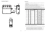
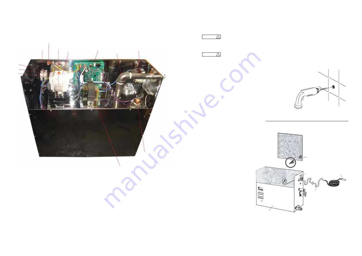
Steam Generator Parts

NOTE:  

For illustrative purposes only.

Some components may be omitted or altered for clarity.
Do not use for wiring, repair or other purposes not related
to component identification. 

Relay

Contactor

Board

Transformer

Water level probe

Solenoid Valve

Steam Outlet

Neutral

Earth

L1

L2

L3

Diagram 1

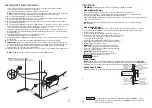
Installing the Remote Temperature Probe

for SAWO Controls

Diagram 2

DRAWING NOT 
TO SCALE

SAWO Steam Generator
(shown with cover removed and NOT installed)

Temperature
Sensing Probe

Knock-out

Temperature

Probe Cable

(9 meters)

Temperature Probe
Connection

Printed 

Circuit 

Board 

Component 

shown for

illustrative 

purpose

1. Determine the location of the Remote Temperature Probe.

The Remote Temperature Probe must be installed: 
a. On a vertical surface 
b. 1.2-1.5 meters above the floor
c. Away from the steam head
d. Not exposed to direct steam emission.

The probe has an integral 9 meter 
cable. Insure that the probe and/or 
steam generator are located accordingly.  
Contact a SAWO technical service 
representative if a longer cable is 
required.

2. Drill an 8mm hole in the wall as 

shown in Diagram 1. Do not 
oversize or undersize the hole. 
Clean area thoroughly.

3. Remove the knock-out from the 

steam generator jacket as shown in 
Diagram 2.

4. Insert the remote temperature 

probe cable through the 
knock-out and connect to the 
connector on the steam 
generator printed 
circuit board marked "TEMP 
PROBE" as shown 
in Diagram 2.

NOTE: 

For illustrative purposes only.
Consult. with qualified designer, 
architect or contractor for steam 
room construction details.


Install the SAWO Control according to the installation and operation 

instructions supplied with the control. Failure to do so may result in an inoperative 
control and a hazardous condition.

!

CAUTION

                      The Remote Temperature Probe is for use with SAWO Control only. Do not use 
any other controls. Do not use any other temperature probe with the SAWO control. 
Noncompatible products may result in an inoperative control and a hazardous condition.

!

CAUTION

STS

230V 1N~
kW

KATSO OHJE

ISTA 

BEACHTEN SIE DIE 

ZUSÄTZLICHEN 

WICHTIGEN 

ANWEISUNGEN I

N DER 

BEDIENUNGSAN

LEITUNG

READ THE 

MANUAL

 FOR 

ADDITIONAL

 IMPOR

TANT 

INSTRUCTIONS

LÄGG  MÄRKE

 TILL DE 

VIKTIGA


15

Содержание STS120-3

Страница 1: ...NUAL STEAMBATH GENERATOR SYSTEMS Congratulations on your purchase of a SAWO Steam Generator Please read the manual carefully before using the steam generator STS60 1 STS60 3 STS45 1 STS45 3 STS90 1 ST...

Страница 2: ...discomfort Do not use the Steam Room if you have been recently drinking alcohol Installation of non skid floor materials or the use of proper footwear is a must at all times when inside the Steam Room...

Страница 3: ...unqualified persons may void the warranty The Steam Room must be fully enclosed complete with walls door flooring and ceiling We recommend rubber linings e g gaskets for the door to effectively seal t...

Страница 4: ...per and automatic safety valve operation DO NOT connect a shut off valve or a plug at safety valve outlet DO NOT connect a shut off valve in steam supply pipe 4 Locating the Steam Generator 1 2 3 4 5...

Страница 5: ...generator or one that is capable of being locked in the open position For single phase units use two wire supply source and equipment grounding wire Electrical _______________________________________...

Страница 6: ...electrician for electrical installation _________________________________________________ _________________________________________________ TO AVOID EQUIPMENT DAMAGE DO NOT CONNECT POWER SUPPLY DIRECT...

Страница 7: ...ector for Automatic drain Optional Tandem Cable for connecting 2 5 steam generators in tandem 1 Turn on control Follow specific instruction sheet provided with controls 2 Steam will begin to appear in...

Страница 8: ...G Start with one drop to gauge strength and suitability Limit to a maximum of a few drops during a steambathing session Some people may find that the aroma makes dizzy and the user should exit the ste...

Страница 9: ...representative if a longer cable is required 2 Drill an 8mm hole in the wall as shown in Diagram 1 Do not oversize or undersize the hole Clean area thoroughly 3 Remove the knock out from the steam ge...

Страница 10: ...size or undersize the hole Step 3 Step 4 67 mm 25 mm 25 mm A B C D Wall Wall Do not route the control or temperature sensor wiring inside conduit together with power lines or close to hot water or ste...

Страница 11: ...play as a confirmation of the new value you have selected The Set Point indicator shows the desired temperature NOT the actual temperature Temperature can be adjusted in 0 5 degree increments from 40...

Страница 12: ...three phase connection and 2 blue wires for single phase connection Remove the nuts and washers that fasten the heating element Detach the heating element from the unit Brush the affected area of the...

Отзывы: