background image

16

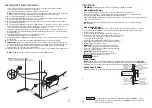
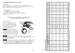
5.  Route the end of the temperature probe cable with the 

temperature probe through the wall into the steam room 
as shown in Diagram 3.

IMPORTANT NOTE:

  Do not strain, staple, pinch or otherwise

damage the probe cable. 

6.  With a minimal length of the cable exposed apply silicone

(provided) to the hole in the wall as required to create a 
moisture seal as shown in Diagram 3.

7. 


Insure a minimum of 6mm of the temperature

bulb is exposed to the air. Failure to do so may result in an
inoperative control and a hazardous condition.


The exposed area of the temperature bulb 

mustbe free of silicone or any materials that prevent direct 
exposure to the steam room air. Failure to do so may 
interfere with the ability to sense temperature and may 
result in excessive steam room temperatures. 

INSTALLED REMOTE 

TEMPERATURE PROBE

6mm

Minimum

13mm

Maximum

Silicone Sealant

Cable

Wall

SECTIONAL VIEW

Steam Room Interior

Diagram 3

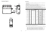
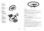
Diagram 4

Installing the Remote Temperature Probe

(cont.)

!

WARNING

!

WARNING

Push the temperature cable and bulb into hole as required 
to leave minimum 6mm, maximum 13mm of the bulb 
exposed as shown below.

17

1.

Use only mild soap and water on a soft cloth to clean the control.

Care Tips for Control

2.

Do not use abrasive cleansers

N

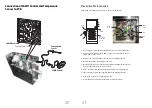
Step 1

Step 2

Do not oversize or undersize the hole.

Step 3

Step 4

67 mm

25 mm

25 mm

A

B

C

D

Wall

Wall

                      Do not route the control or temperature sensor wiring inside conduit 
together with power lines or close to hot water or steam piping.  Doing so may result in 
an inoperative or hazardous installation. Do not alter or modify the control. Doing so may 
result in an inoperative or hazardous installation.

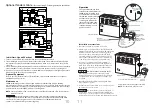
Determine the desired installation location of the control. 
The SAWO control is designed to be installed inside or 
outside the steam room   a matter of personal preference.

The control cable length is 7.5 m. Insure that the control 
and/or steam generator are located accordingly. 

Turn on power to the steam generator and test the control 
to verify correct connections. Test per the instructions.
Proceed with installation and verification of proper control
function.

Route the control cable to the steam generator. 
Connect the connector to the steam generator.

!

CAUTION

Installation Instructions

SAWO Control 

Installation, Operation & Maintenance Manual

IMPORTANT:

   Turn power to the steam generator OFF

before installing the control. Failure to turn  the power
off will result in an inoperable control.

IMPORTANT:

   Do not strain, staple pinch or otherwise

damage the control cable. Route cable as required to 
permit replacement.

NOTE:

   The connector is keyed.

IMPORTANT NOTE:

   Turn power to the steam generator OFF before installing the control.

Failure to turn the power off will result in an inoperable control.

Содержание STS120-3

Страница 1: ...NUAL STEAMBATH GENERATOR SYSTEMS Congratulations on your purchase of a SAWO Steam Generator Please read the manual carefully before using the steam generator STS60 1 STS60 3 STS45 1 STS45 3 STS90 1 ST...

Страница 2: ...discomfort Do not use the Steam Room if you have been recently drinking alcohol Installation of non skid floor materials or the use of proper footwear is a must at all times when inside the Steam Room...

Страница 3: ...unqualified persons may void the warranty The Steam Room must be fully enclosed complete with walls door flooring and ceiling We recommend rubber linings e g gaskets for the door to effectively seal t...

Страница 4: ...per and automatic safety valve operation DO NOT connect a shut off valve or a plug at safety valve outlet DO NOT connect a shut off valve in steam supply pipe 4 Locating the Steam Generator 1 2 3 4 5...

Страница 5: ...generator or one that is capable of being locked in the open position For single phase units use two wire supply source and equipment grounding wire Electrical _______________________________________...

Страница 6: ...electrician for electrical installation _________________________________________________ _________________________________________________ TO AVOID EQUIPMENT DAMAGE DO NOT CONNECT POWER SUPPLY DIRECT...

Страница 7: ...ector for Automatic drain Optional Tandem Cable for connecting 2 5 steam generators in tandem 1 Turn on control Follow specific instruction sheet provided with controls 2 Steam will begin to appear in...

Страница 8: ...G Start with one drop to gauge strength and suitability Limit to a maximum of a few drops during a steambathing session Some people may find that the aroma makes dizzy and the user should exit the ste...

Страница 9: ...representative if a longer cable is required 2 Drill an 8mm hole in the wall as shown in Diagram 1 Do not oversize or undersize the hole Clean area thoroughly 3 Remove the knock out from the steam ge...

Страница 10: ...size or undersize the hole Step 3 Step 4 67 mm 25 mm 25 mm A B C D Wall Wall Do not route the control or temperature sensor wiring inside conduit together with power lines or close to hot water or ste...

Страница 11: ...play as a confirmation of the new value you have selected The Set Point indicator shows the desired temperature NOT the actual temperature Temperature can be adjusted in 0 5 degree increments from 40...

Страница 12: ...three phase connection and 2 blue wires for single phase connection Remove the nuts and washers that fasten the heating element Detach the heating element from the unit Brush the affected area of the...

Отзывы: