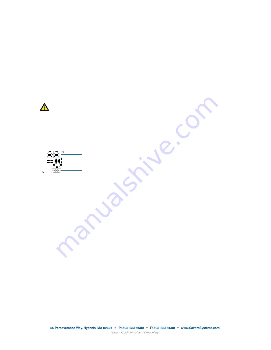
Removing and Replacing a Transorb Board
Transorb boards are used to connect modules in enclosures to SmartLighting controllers. A maximum of
4 transorb boards (64 addresses) are supported when using the SSL-P002 and a maximum of 16 transorb
boards are supported when using the SSL-P018 (256 addresses). Up to 4 transorb boards can be installed
in an ENC-4000 (4-module enclosure) and up to 2 transorb boards can be installed in an ENC-2000 (2-
module enclosure).
Two enclosure models are available to house either two-modules or four-modules. The enclosures can
be recessed, flush-mounted or surface-mounted for both the models. The enclosures can be mounted
two or more units high. Each enclosure contains a voltage divider/barrier to isolate high voltage from low
voltage.
CAUTION
: Keep these wires on their respective side of the enclosure. Do not cross over or
under the voltage barrier with wires.
To replace legacy LiteTouch transorb boards with Savant SmartLighting transorb boards, do the following.
1. Locate and remove the legacy transorb board in the upper left corner of the module enclosure.
2. Add the Savant SmartLighting transorb board (ENC-TRANS-xx) to the enclosure where the legacy
transorb board was removed.
Wiring Modules
1. Locate the 5-pin port on the Savant transorb board.
!"#$%&&'$()'**+
!"#$%&&'()$*+,-./'0,12,"*"$#
62
LiteTouch Installation and Troubleshooting Manual
Plug a data cable into the five-pin connector on the transorb board, and
plug the other end into the DATA IN port on the first module.
2. Connect another data cable to the DATA OUT port on the first module
and to the DATA IN port on the second module.
3. Continue to connect a cable to the DATA OUT port of one module and
the DATA IN port of the next module until all control modules in the
enclosure are connected.
!
"#$
☞
!"#"$%&'&()$*+,-$(+#$.+((,.#$#+$/+%,'$-0//1&,-2$3+3,(#"'4$.+(#".#$*"#"$&(/0#$
3+*01,-2$+'$3"&(#"&(,*$.+(#".#$*"#"$&(/0#$3+*01,-5$611$3+*01,-$#7"#$30-#$8,$
&(.10*,*$&($#7,$*"#"$%&'&()$7"9,$!6:6$;<$"(*$!6:6$=>:$/+'#-5$
When finished, all control modules in each enclosure should be connected
in a string to the first module (top module), which is connected to the tran-
sorb board via the 5-pin connector.
,$-."/'0"1&2#3-)#
42/)$()-
In large installations (more than eight enclosures), or when you have mul-
tiple enclosure locations, you can string enclosures together to reduce the
number of data homeruns to the CCU. While this helps to simplify the
wiring, you should be aware that an early circuit breaker failure in the
RJ-45 Ports
5-pin Phoenix Ports
Savant Transorb Board
2. Plug in the Module Jumper Wire (ENC-MJ22) with the 5-pin connectors on both ends (22-gauge) to the Savant
transorb board.
3. Connect the other end of the 5-pin connector on the Module Jumper Wire also with a 5-pin connector from the
Savant transorb board to the Data In port on the first module.
4. Connect the Data Out port on the first module to the Data In port on the second module using the Module Jumper
Wire
5. Continue until all modules in the enclosure are connected with the Module Jumper Wire.
6. Connect the line feeds (electrical loads) to each module.
7. Interconnect the line feeds to the modules, ground bar and neutral bar
8. Connect the 120 volt feed from the Module Enclosure to the electrical panel.
9. Connect up to 16 Module Enclosures or 16 transorb boards per port on the SSL-P018 with CAT 5/6 cable.
5. SSL Controller Installation
There are two models of controllers for the SmartLighting configuration: SSL-P002 and SSL-P018.
They can both be powered over a CAT 5/6 cable with PoE. If PoE is not available, the SSL-P002 can be powered with an
external 5V DC power supply (PWR-5025). The SSL-P018 can be powered with an external 12V DC power supply
(PWR-12125).
Front View of SSL-P002
Rear View of SSL-P002
101612 009-0766-00
16 of 65
Document based upon target specifications. Specifications subject to change prior to final product release.
Savant Transorb Board
3. Locate and remove the legacy LiteTouch Power Supply modules in the enclosure. The power supplies
are no longer necessary. The Savant SKL-1000 or SKL-4000 Keypad Link provide power to the
keypads.
4. Install other lighting control modules where the power supply modules were removed, if required.
5. Locate the 5-pin port on the transorb board.
6. Plug in the Module Jumper Wire (ENC-MJ22) with the 5-pin connectors on both ends (22-gauge) to
the Savant transorb board.
7. Connect the other end of the 5-pin connector on the Module Jumper Wire with a 5-pin connector
from the Savant transorb board to the Data In port on the first module.
8. Connect the Data Out port on the first module to the second module using the Module Jumper Wire.
9. Repeat the previous steps in this procedure for all transorb boards on the SSL-P002 and the SSL-
P018.
140915 009-0885-01 Savant SmartLighting Control Conversion Application
9 of 22


