background image


å

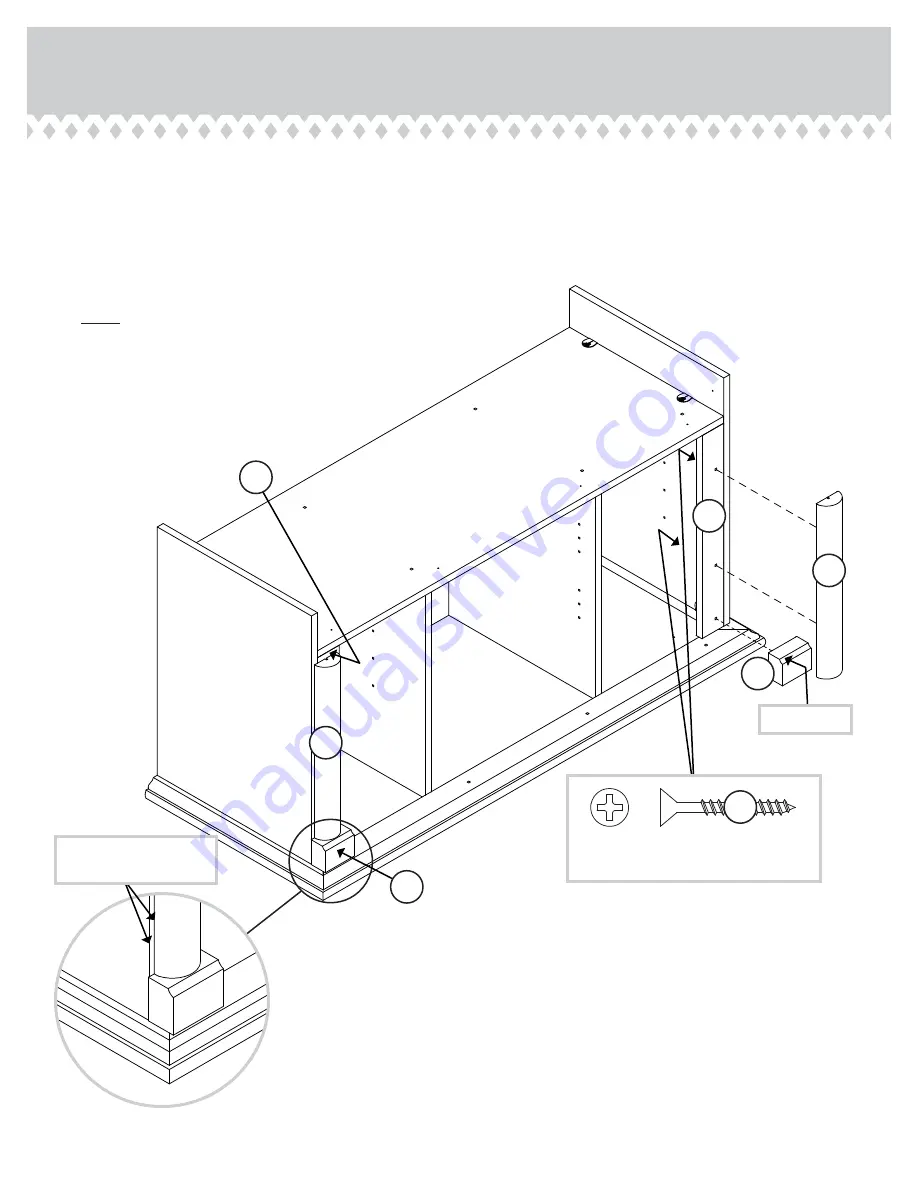
Fasten the UPPER PLINTHS (O) to the END 
MOLDINGS (S and T). Use two BLACK 1-1/4" 
FLAT HEAD SCREWS (NN). 


å

Fasten the SIDE MOLDINGS (M) to the END 
MOLDINGS (S and T). Use four BLACK 1-1/4" FLAT 
HEAD SCREWS (NN). 


å

NOTE: There are no pre-drilled holes in the SIDE 
MOLDINGS. The SCREWS will tighten into the groove. 

Step 8

411864

www.sauder.com/services

Page 12

M

M

T

S

Curved edge

BLACK 1-1/4" FLAT HEAD SCREW

(6 used in this step)

NN

O

O

The END MOLDINGS 
will set in from the edge.

Содержание Palladia 411864

Страница 1: ...NOTE THIS INSTRUCTION BOOKLET CONTAINS IMPORTANT SAFETY INFORMATION PLEASE READ AND KEEP FOR FUTURE REFERENCE English pg 1 23 Français pg 24 27 Español pg 28 31 Lot 357575 11 25 13 Purchased __________________ Be sure to give us a ring before making any returns 1 800 523 3987 Panel TV Stand Palladia Collection 411864 Smart stand for the idiot box ...

Страница 2: ... is designed for use with televisions weighing less than 95 pounds Never use with a TV that weighs more The size of the television front to back and side to side must fit within the space defined in the diagram Never place the front edge of the TV past the front edge of the TV support shelf or stop molding if equipped Never allow the sides of the TV to extend past the side edges of the TV support su...

Страница 3: ...T 1 D LEFT UPRIGHT 1 E TOP 1 F BOTTOM 1 G BACK 1 H DOOR 2 I LARGE ADJUSTABLE SHELF 2 J SMALL ADJUSTABLE SHELF 2 K BASE 1 L LOWER PLINTH 2 M SIDE MOLDING 2 N BOTTOM MOLDING 1 O UPPER PLINTH 2 P FRONT MOLDING 1 Q RIGHT MOLDING 1 R LEFT MOLDING 1 S RIGHT END MOLDING 1 T LEFT END MOLDING 1 U RIGHT HINGE MOLDING 1 V LEFT HINGE MOLDING 1 W VALANCE 1 X BRACE 1 Y HALF DISK 2 411864 www sauder com services...

Страница 4: ...METAL PIN 20 JJ SILVER 5 8 FLAT HEAD SCREW 8 QQ MOLDING CONNECTOR 2 GG FF HINGE SPACER 4 EE HINGE 4 KNOB 2 HH NAIL 36 TT HIDDEN CAM 4 AA2 CAM DOWEL 4 BB2 Refer to the last step for proper location and application WARNING LABEL 1 LL WARNING Never use this furniture with a TV that is too large or too heavy Severe injury or death can occur The TV and furniture will be unstable and may tip The TV must...

Страница 5: ...it on a carpeted floor or on the empty carton to avoid scratching your unit or the floor å To begin assembly push a SAUDER TWIST LOCK FASTENER Z into the large holes in the ENDS A and B Repeat this step for the BOTTOM F 411864 www sauder com services Page 5 8 used Do not tighten the TWIST LOCK FASTENERS in this step Z A B ...

Страница 6: ...å Push four HIDDEN CAMS AA2 into the HINGE MOLDINGS U and V Step 2 411864 www sauder com services Page 6 Do not tighten the HIDDEN CAMS in this step Arrow AA2 U V 4 used Hole Arrow ...

Страница 7: ...ING CONNECTORS GG into the notches in the MOLDINGS P Q and R Step 3 411864 www sauder com services Page 7 Use your hammer to tap the MOLDING CONNECTOR GG into the notches in the MOLDINGS Flat end Flat end P Q R GG GG ...

Страница 8: ...INGS P Q and R to the TOP E Use eight BLACK 1 1 4 FLAT HEAD SCREWS NN Step 4 411864 www sauder com services Page 8 E P Q R BLACK 1 1 4 FLAT HEAD SCREW 8 used in this step NN Rounded edge S u r f a c e w i t h h o l e s ...

Страница 9: ...ert the dowel end of the FASTENER into the hole of the adjoining part NOTE The dowel end of the FASTENER must remain fully inserted in the hole of the adjoining part while locking the FASTENER 2 Tighten the FASTENER with a Phillips screwdriver as tight as possible Dowel end 6 3 4 7 5 8 Finished edge B C D E R JJ JJ Surface with 6 holes Surface with 12 holes Surface with TWIST LOCK FASTENERS Rounde...

Страница 10: ...nd D Use four BLACK 1 7 8 FLAT HEAD SCREWS MM å Fasten the RIGHT END A to the BOTTOM F and RIGHT MOLDING Q Tighten four TWIST LOCK FASTENERS 411864 www sauder com services Page 10 Unfinished surface Surface without TWIST LOCK FASTENERS Q A B C D F These holes must be here BLACK 1 7 8 FLAT HEAD SCREW 4 used in this step MM ...

Страница 11: ...e BRACKETS are even with the edges of the END MOLDINGS å Fasten the END MOLDINGS S and T to the ENDS A and B Use six BLACK 9 16 LARGE HEAD SCREWS RR through the METAL BRACKETS and into the ENDS 411864 www sauder com services Page 11 A B S S T T CC CC Surface without METAL BRACKETS Surface without METAL BRACKETS Finished edge BLACK 9 16 LARGE HEAD SCREW 12 used for the METAL BRACKETS RR ...

Страница 12: ... the END MOLDINGS S and T Use four BLACK 1 1 4 FLAT HEAD SCREWS NN å NOTE There are no pre drilled holes in the SIDE MOLDINGS The SCREWS will tighten into the groove Step 8 411864 www sauder com services Page 12 M M T S Curved edge BLACK 1 1 4 FLAT HEAD SCREW 6 used in this step NN O O The END MOLDINGS will set in from the edge ...

Страница 13: ...N CAMS Step 9 411864 www sauder com services Page 13 BB2 BB2 U V Finished edge Finished edge Surface with HIDDEN CAMS Surface without HIDDEN CAMS Start Tighten Arrow Minimum 190 degrees Caution Risk of damage or injury HIDDEN CAMS must be completely tightened HIDDEN CAMS that are not completely tightened may loosen and parts may separate To completely tighten Arrow Maximum 210 degrees T S ...

Страница 14: ... 16 LARGE HEAD SCREWS RR å Fasten the HINGE MOLDINGS U and V to the BOTTOM F Use two BLACK 1 7 8 FLAT HEAD SCREWS MM Step 10 411864 www sauder com services Page 14 E F V CC CC U BLACK 9 16 LARGE HEAD SCREW 4 used for the METAL BRACKETS RR BLACK 1 7 8 FLAT HEAD SCREW 2 used in this step MM ...

Страница 15: ...BROWN 7 16 LARGE HEAD SCREWS SS å Fasten the VALANCE W to the TIE PLATES on the FRONT MOLDING P Use four BROWN 7 16 LARGE HEAD SCREWS SS Step 11 411864 www sauder com services Page 15 P W DD Wider edge BROWN 7 16 LARGE HEAD SCREW 8 used for the TIE PLATES SS DD ...

Страница 16: ... are even with the edges of the BRACE å Fasten the BRACE X to the ENDS A and B and BOTTOM F Use six BLACK 9 16 LARGE HEAD SCREWS RR through the METAL BRACKETS and into the ENDS and BOTTOM Step 12 411864 www sauder com services Page 16 BLACK 9 16 LARGE HEAD SCREW 12 used for the METAL BRACKETS RR A B F X CC CC CC X ...

Страница 17: ...and BOTTOM MOLDING N to the BRACE X Use eight BROWN 1 FLAT HEAD SCREWS OO Step 13 411864 www sauder com services Page 17 K N X Be sure the holes are closest to this long edge BROWN 1 FLAT HEAD SCREW 8 used in this step OO ...

Страница 18: ...E X Use four BLACK 1 1 4 FLAT HEAD SCREWS NN Step 14 411864 www sauder com services Page 18 L L L L X Y Y Y The larger hole must be facing up BLACK 1 1 4 FLAT HEAD SCREW 4 used in this step NN BROWN 1 FLAT HEAD SCREW 2 used for the HALF DISK OO Flat edge Flat edge Flip the LOWER PLINTHS L over Flip the LOWER PLINTHS L over Y ...

Страница 19: ...å NOTE Be sure to tap NAILS into the holes that line up over the UPRIGHTS C and D å NOTE Perforations have been provided for access through the BACK Carefully cut out the holes needed Step 15 411864 www sauder com services Page 19 Do not stand the unit upright without the BACK fastened The unit may collapse Caution U n fi n i s h e d s u r f a c e NAIL 36 used in this step TT F G This perforation s...

Страница 20: ... four HINGE SPACERS FF and four HINGES EE to the DOORS H Use eight SILVER 5 8 FLAT HEAD SCREWS QQ Step 16 411864 www sauder com services Page 20 H H FF FF EE EE SILVER 5 8 FLAT HEAD SCREW 8 used in this step QQ ...

Страница 21: ...way out of the slot Retighten the screw before you mount the HINGE to the MOLDING å Fasten a KNOB HH to the DOOR H Use a GOLD 1 MACHINE SCREW PP å Peel two FELT DISC from the FELT DISC CARD II and stick them on the DOOR H where they come in contact with the UPRIGHT C å Repeat this step for the other DOOR H Step 17 411864 www sauder com services Page 21 GOLD 1 MACHINE SCREW 2 used in this step PP C...

Страница 22: ...turns then turn the adjusting screw in or out Tighten the mounting screw after making adjustments å To adjust the DOORS up and down vertical loosen both vertical adjustment screws Move the DOORS up or down to the desired location Tighten the screws after making adjustments å To adjust the DOORS in or out depth loosen the mounting screw one turn and move the DOORS in or out as needed Tighten the mo...

Страница 23: ...S I and J onto the METAL PINS å Apply the WARNING LABEL LL to the TOP E You should be able to read the label when the TV is removed from the unit When the TV is in place it should hide the label Peel off the backing and apply the label as shown in the diagram å NOTE This is a permanent label intended to last for the life of the product Once applied do not try to remove it å NOTE Please read the ba...

Страница 24: ...on Comparer la Liste de pièces ci dessous avec la PART IDENTIFICATION du manuel en anglais pour vous familiariser avec les pièces avant l assemblage REMARQUE CE MANUEL D INSTRUCTIONS CONTIENT D IMPORTANTES INFORMATIONS RELATIVES À LA SÉCURITÉ À LIRE ET CONSERVER POUR TOUTE RÉFÉRENCE FUTURE Z FIXATION TWIST LOCK 8 AA2 EXCENTRIQUE ESCAMOTABLE 4 BB2 CHEVILLE D EXCENTRIQUE 4 CC CONSOLE EN MÉTAL 14 DD ...

Страница 25: ...seur Si le téléviseur comporte un tube cathodique à image la robe du tube à image peut dépasser l arrière de la tablette de support S assurer d apposer l étiquette d avertissement tel qu il l est indiqué dans la dernière étape d assemblage L étiquette fournit d importantes informations relatives à la sécurité ÉTAPE 4 Fixer les MOULURES P Q et R au DESSUS E Utiliser huit VIS NOIRES TÊTE PLATE 32 mm...

Страница 26: ... NOIRES TÊTE LARGE 14 mm RR REMARQUE S assurer que les CONSOLES sont à fleur des chants de l ENTRETOISE Fixer l ENTRETOISE X aux EXTRÉMITÉS A et B et au DESSOUS F Utiliser six VIS NOIRES TÊTE LARGE 14 mm RR à travers les CONSOLES EN MÉTAL et dans les EXTRÉMITÉS et DESSOUS ÉTAPE 11 Fixer quatre PLAQUES DE LIAISON DD à la MOULURE AVANT P Utiliser quatre VIS MARRON TÊTE LARGE 11 mm SS Fixer le LAMBREQ...

Страница 27: ...e lisible lorsque le téléviseur est enlevé de l élément Lorsque le téléviseur est en place il doit la dissimuler Décoller le film protecteur et apposer l étiquette comme l indique le schéma REMARQUE Cette étiquette permanente est prévue pour durer pendant toute la vie du produit Une fois apposée ne pas essayer de la retirer REMARQUE Prière de lire attentivement les importantes informations concerna...

Страница 28: ...blaje NOTA ESTE FOLLETO DE INSTRUCCIONES CONTIENE INFORMACIÓN IMPORTANTE SOBRE LA SEGURIDAD POR FAVOR LEA Y GUÁRDELO PARA REFERENCIA EN EL FUTURO LISTA DE PARTES ITEM DESCRIPCIÓN CANTIDAD Z SUJETADOR TWIST LOCK 8 AA2 EXCÉNTRICO ESCONDIDO 4 BB2 PASADOR DE EXCÉNTRICO 4 CC SOPORTE DE METAL 14 DD PLACA DE CONEXIÓN 4 EE BISAGRA 4 FF ESPACIADOR DE BISAGRA 4 GG CONECTOR DE MOLDURA 2 HH TIRADOR 2 II TARJE...

Страница 29: ...EXTREMO S y T a los EXTREMOS A y B Pase seis TORNILLOS NEGROS DE CABEZA GRANDE de 14 mm RR a través de los SOPORTES DE METAL y dentro de los EXTREMOS PASO 1 Ensamble la unidad sobre un piso alfombrado o sobre el cartón vacío para evitar rayar la unidad o el piso Para comenzar el ensamblaje empuje un SUJETADOR TWIST LOCK SAUDER Z dentro de los agujeros grandes de los EXTREMOS A y B Repita este paso...

Страница 30: ...a RIOSTRA Fije la RIOSTRA X a los EXTREMOS A y B y al FONDO F Pase seis TORNILLOS NEGROS DE CABEZA GRANDE de 14 mm RR a través de los SOPORTES DE METAL y dentro de los EXTREMOS y del FONDO PASO 11 Fije cuatro PLACAS DE CONEXIÓN DD a la MOLDURA DELANTERA P Utilice cuatro TORNILLOS MARRONES DE CABEZA GRANDE de 11 mm SS Fije la CORNISA W a las PLACAS DE CONEXIÓN en la MOLDURA DELANTERA P Utilice cuat...

Страница 31: ...te hacia el interior o hacia el exterior Apriete el tornillo de montaje después de hacer los ajustes Para ajustar las PUERTAS hacia arriba o hacia abajo vertical afloje los dos tornillos de ajuste Mueva las PUERTAS hacia arriba o hacia abajo a la ubicación deseada Apriete los tornillos después de hacer los ajustes Para ajustar las PUERTAS hacia atrás o hacia adelante profundidad afloje el tornillo d...

Страница 32: ...mmended size of the TVs it will safely support Risk of injury or death TVs can be very heavy Plus the weight and location of the picture tube tends to make TVs unbalanced and prone to tipping forward Furniture items such as general purpose utility carts tables or dressers may become unstable and tip if a TV is set on them A TV must only be set on furniture specifically designed to support a televis...

Страница 33: ...des téléviseurs qu ils peuvent supporter en toute sécurité Risque de blessures graves voire mortelles Les téléviseurs peuvent être très lourd De plus le poids et l emplacement du tube image ont tendance à rendre les téléviseurs instables et enclins à tomber vers l avant Les meubles tels que les dessertes à tout usage les tables ou les commodes risquent de se renverser si on pose un téléviseur dess...

Страница 34: ...iones o la muerte Los televisores pueden ser muy pesados Además el peso y la ubicación del tubo de imagen tienden a causar la inestabilidad de televisores y propensa a volcarse hacia adelante Los artículos mobiliarios tales como carritos de uso general mesas o cómodas pueden hacerse inestables y inclinarse si coloca un televisor encima Un televisor debe colocarse solamente sobre el mobiliario dise...

Страница 35: ...seront garanties uniquement pendant la période restante de la garantie originale SAUDER NE SERA EN AUCUN CAS RESPONSABLE de TOUT DOMMAGE ACCESSOIRE OU CONSÉCUTIF DE TOUTE SORTE et lesdits dommages sont EXCLUS DE LA PRÉSENTE GARANTIE à savoir perte d utilisation démontage transport main d ceuvre ou dommages matériels sur ou à proximité du produit Certains États ou provinces ne permettant pas l excl...

Страница 36: ...old true to his core values of innovation integrity servanthood and stewardship Sauder products are made with environmentally responsible materials and world class manufacturing processes Our 2 000 dedicated employees in Archbold Ohio along with our global manufacturing partners are committed to providing you furniture with great value style and quality From our family to you Enjoy Kevin J Sauder ...

Отзывы: