background image

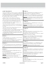
PASO 7

Fije las PATAS DE EXTREMO (I) a las RIOSTRAS (J y K). Utilice 
cuatro TORNILLOS ALLEN de 35 mm (12) utilizando la LLAVE 
ALLEN (8).

NOTA: No apriete los TORNILLOS ALLEN en este momento.

PASO 8

Fije las PATAS DE EXTREMO (I) y la RIOSTRA FRONTALE (K) 
al FONDO (D). Utilice siete TORNILLOS ALLEN de 30 mm (13) 
utilizando la LLAVE ALLEN (8).

Fije la RIOSTRA POSTERIOR (J) al FONDO (D). Utilice dos 
TORNILLOS DE CABEZA REDONDA de 13 mm (16) por entre los 
rebordes de la RIOSTRA POSTERIOR y por entre el FONDO.

NOTA: Apriete todos los TORNILLOS ALLEN.

PASO 6

Precaución
No coloque la unidad en posición vertical hasta que se fi je el 
DORSO. La unidad podría caerse.

Cuidadosamente voltee la unidad para que repose sobre los bordes 
delanteros. Desdoble el DORSO (E) y colóquelo sobre la unidad.

Los márgenes a lo largo de todos los bordes del DORSO (E) 
deben estar uniformes. Empuje sobre las esquinas opuestas de la 
unidad si es requerido para hacerla "cuadrada."

Fije el DORSO (E) a la unidad utilizando los CLAVOS (9).

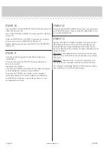
PASO 5

Fije el FONDO (D) a los EXTREMOS (B y C). Utilice cuatro 
TORNILLOS DE CABEZA PERDIDA de 41 mm (11).

NOTA: Asegúrese de insertar los PASADORES DE MADERA 
sujetados a los EXTREMOS dentro de los agujeros del FONDO.

PASO 4

Inserte cinco EXCÉNTRICOS ESCONDIDOS (3) dentro de los 
EXTREMOS (B y C) y de la MOLDURA DE PANEL SUPERIOR (F).

Fije el PANEL SUPERIOR (A) a los EXTREMOS (B y C) y a la 
MOLDURA DE PANEL SUPERIOR (F). Apriete los EXCÉNTRICOS 
ESCONDIDOS.

NOTA: Asegúrese de que los PASADORES DE MADERA sujetados 
a los EXTREMOS y a la MOLDURA DE PANEL SUPERIOR se 
inserten dentro de los agujeros del PANEL SUPERIOR (A).

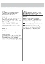
PASO 1

Ensamble la unidad sobre un piso alfombrado o sobre el cartón 
vacío para evitar rayar la unidad o el piso.

Atornille siete BIELAS DE EXCÉNTRICO (1) dentro del PANEL 
SUPERIOR (A), del EXTREMO IZQUIERDO (B) y del EXTREMO 
DERECHO (C).

PASO 2

Empuje doce PASADORES DE MADERA (4) dentro de los 
EXTREMOS (B y C) y de la MOLDURA DE PANEL SUPERIOR (F). 
Asegúrese de utilizar los agujeros correspondientes indicados.

PASO 3

Empuje dos EXCÉNTRICOS ESCONDIDOS (3) dentro de la 
MOLDURA DE PANEL SUPERIOR (F).

Fije la MOLDURA DE PANEL SUPERIOR (F) a los EXTREMOS (B y C). 
Apriete los EXCÉNTRICOS ESCONDIDOS.

NOTA:  Asegúrese de seguir el diagrama al lado derecho sobre la 
manera de apretar el EXCÉNTRICO ESCONDIDO.

NOTA:  Asegúrese de que los PASADORES DE MADERA se 
inserten en los agujeros en los EXTREMOS.

ADVERTENCIA

 El uso de un televisor demasiado pesado o grande es peligroso. 
Un televisor demasiado pesado generará riesgo de caída, lo cual 
podría causar lesiones graves o muerte. Un televisor demasiado 
grande para el espacio disponible puede ser empujado o 
golpeado por accidente, causando que éste se salga del mueble o 
se caiga.

• Verifi que el tamaño y peso del televisor. ¡Compárelo al diagrama 
abajo - antes de comenzar el ensamblaje!

• Esta unidad Sauder está diseñada para ser usada con 
televisores cuyo peso sea inferior a 16 Kg. Nunca la use para un 
televisor de mayor peso.

• El tamaño del televisor, del frente al extremo posterior, y de 
un lado al otro, debe caber dentro del espacio defi nido en el 
diagrama.

• Nunca coloque el borde frontal del televisor más adelante del 
borde frontal del estante de soporte del televisor (o de la moldura 
de tope, si existe tal equipamiento)

• Nunca permita que los lados del televisor se extiendan más allá 
de los bordes laterales de la superfi cie de soporte del televisor.

• Si el televisor tiene un tubo CRT, el cono del mismo puede 
extenderse más allá de la parte trasera del estante de soporte.

• Asegúrese de colocar la etiqueta de advertencia según las 
instrucciones, en el último paso del armado. La etiqueta ofrece 
información importante de seguridad.

Page 22

www.sauder.com

420035

Содержание North Avenue 420035

Страница 1: ... what we have in storage Display Cabinet North Avenue Collection Model 420035 NOTE THIS INSTRUCTION BOOKLET CONTAINS IMPORTANT SAFETY INFORMATION PLEASE READ AND KEEP FOR FUTURE REFERENCE English pg 1 17 Français pg 18 20 Español pg 21 24 Lot 392458 Date Purchased __________________ 06 15 16 Be sure to give us a ring before making any returns 1 800 445 1527 ...

Страница 2: ...it to the diagram below before you begin assembly This Sauder unit is designed for use with televisions weighing less than 35 pounds Never use with a TV that weighs more The size of the television front to back and side to side must fit within the space defined in the diagram Never place the front edge of the TV past the front edge of the TV support shelf or stop molding if equipped Never allow the ...

Страница 3: ...ilar parts from each other Use this part identification to help identify similar parts Now you know our ABCs Part Identification A TOP 1 B LEFT END 1 C RIGHT END 1 D BOTTOM 1 E BACK 1 F TOP MOLDING 1 G ADJUSTABLE SHELF 1 H DOOR 2 I END LEG 2 J BACK BRACE 1 K FRONT BRACE 1 A B C D E F G H H I I J K Page 3 www sauder com 420035 ...

Страница 4: ... la surface Never use this furniture with a TV that is too large or too heavy Severe injury or death can occur The TV and furniture will be unstable and may tip The TV must weigh less than The base of the TV must be able to sit completely on the shelf Refer to instruction book for complete safety information Note This is a permanent label Do not try to remove Surface will be damaged Nunca use este...

Страница 5: ...com services tips Step 1 å Assemble your unit on a carpeted floor or on the empty carton to avoid scratching your unit or the floor å Turn seven CAM SCREWS 1 into the TOP A LEFT END B and RIGHT END C B C A 1 7 used Page 5 www sauder com 420035 Remember Righty tighty Lefty loosey ...

Страница 6: ...å Push twelve WOOD DOWELS 4 into the ENDS B and C and TOP MOLDING F Be sure to use the exact holes shown Step 2 B C F 4 4 4 Page 6 www sauder com 420035 ...

Страница 7: ...o the right on how to tighten the HIDDEN CAM å NOTE Be sure the WOOD DOWELS insert into the holes in the ENDS Step 3 B C F 3 2 1 3 The arrow must point toward the edge of the board 3 This surface will be facing out of the part after it is pushed in the TOP MOLDING F Page 7 www sauder com 420035 The arrow must point toward the edge of the board and CAM SCREW ...

Страница 8: ... A to the ENDS B and C and TOP MOLDING F Tighten the HIDDEN CAMS å NOTE Be sure the WOOD DOWELS in the ENDS and TOP MOLDING insert into the holes in the TOP Step 4 3 3 2 1 3 The arrow must point toward the edge of the board B C F These edges must be even Page 8 www sauder com 420035 A ...

Страница 9: ...D to the ENDS B and C Use four 1 5 8 FLAT HEAD SCREWS 11 å NOTE Be sure the WOOD DOWELS in the ENDS insert into the holes in the BOTTOM Step 5 B C These edges must be even 1 5 8 FLAT HEAD SCREW 4 used in this step 11 D Page 9 www sauder com 420035 ...

Страница 10: ... margins along all four edges of the BACK E Push on opposite corners of your unit if needed to make it square å Fasten the BACK E to your unit using the NAILS 9 Do not stand the unit upright without the BACK fastened The unit may collapse Caution NAIL 16 used in this step 9 E Page 10 www sauder com 420035 Notch Notch ...

Страница 11: ...SCREWS 12 and the ALLEN WRENCH 8 å NOTE Do not tighten the ALLEN SCREWS at this time Step 7 8 1 3 8 ALLEN SCREW 4 used in this step 12 I I J K The flanges should be up Page 11 www sauder com 420035 Side Step Make nachos Optional but recommended These holes must be here ...

Страница 12: ...en the BACK BRACE J to the BOTTOM D Use two 1 2 PAN HEAD SCREWS 16 through the flanges in the BACK BRACE and into the BOTTOM å NOTE Tighten all of the ALLEN SCREWS Step 8 I I J K 1 3 16 ALLEN SCREW 7 used in this step 13 1 2 PAN HEAD SCREW 2 used in this step 16 The flanges should be down D Page 12 www sauder com 420035 8 ...

Страница 13: ...Step 9 Page 13 www sauder com 420035 å Fasten two HINGES 6 to a DOOR H Use four 9 16 FLAT HEAD SCREWS 15 å Repeat this step for the other DOOR H 6 9 16 FLAT HEAD SCREW 8 used in this step 15 6 H ...

Страница 14: ...4 å Stick a BUMPER 7 onto the DOOR H where it comes in contact with the TOP MOLDING F å Repeat this step fastening the other DOOR H to the RIGHT END C Step 10 9 16 FLAT HEAD SCREW 16 used for the HINGES 15 5 5 7 7 H H B C F Page 14 www sauder com 420035 Almost time to celebrate With a nap 3 4 MACHINE SCREW 2 used in this step 14 ...

Страница 15: ...e text below to make needed adjustments å DOOR ADJUSTMENTS To adjust the DOORS from side to side horizontal turn the adjusting screw in or out å To adjust the DOORS in or out depth loosen the mounting screw one turn and move the DOORS in or out as needed Tighten the mounting screw after making adjustments Adjusting screw horizontal Mounting screw depth ...

Страница 16: ...å Insert the METAL PINS 2 into the hole locations of your choice in the ENDS B and C Set the ADJUSTABLE SHELF G onto the METAL PINS Step 12 G 2 B C Page 16 www sauder com 420035 G B ...

Страница 17: ... convernant la sécurité Remarque Cette étiquette est permanente Ne pas essayer de la retirer Causer des dommages à la surface Never use this furniture with a TV that is too large or too heavy Severe injury or death can occur The TV and furniture will be unstable and may tip The TV must weigh less than The base of the TV must be able to sit completely on the shelf Refer to instruction book for comp...

Страница 18: ...ns d assemblage en français avec les schémas étape par étape du manuel d instruction en anglais Chaque étape en français correspond à la même étape en anglais La pièce devant être attachée à l élément est représentée en gris sur les schémas de chaque étape pour plus de précision Comparer la Liste de pièces ci dessous avec la PART IDENTIFICATION du manuel en anglais pour vous familiariser avec les ...

Страница 19: ...ULURE DE DESSUS F sur les EXTRÉMITÉS B et C Serrer les EXCENTRIQUES ESCAMOTABLES REMARQUE S assurer de suivre le schéma à la droite sur la manière de serrer l EXCENTRIQUE ESCAMOTABLE REMARQUE S assurer d insérer les CHEVILLES EN BOIS dans les trous des EXTRÉMITÉS ÉTAPE 2 Enfoncer douze CHEVILLES EN BOIS 4 dans les EXTRÉMITÉS B et C et à la MOULURE DE DESSUS F S assurer de utiliser les trous exacts...

Страница 20: ...ÉS B et C Poser la TABLETTE RÉGLABLE G sur les GOUPILLES EN MÉTAL ÉTAPE 11 Consulter le schéma agrandi pour identifier les pièces des CHARNIÈRES Il faut peut être ajuster les PORTES Suivre les indications ci dessous pour ajuster RÉGLAGES DES PORTES Pour ajuster les PORTES latéralement horizontalement tourner la vis de réglage vers l intérieur ou vers l extérieur Pour ajuster les PORTES vers l intér...

Страница 21: ...ada paso en español corresponde al mismo paso en inglés Se destacan las figuras de cada paso con una tonalidad oscura para mostrar precisamente cual parte se debe montar a la unidad Compare la Lista de Part abajo con la Part Identification en el folleto en inglés para familiarizarse con Las partes de ensamblaje NOTA ESTE FOLLETO DE INSTRUCCIONES CONTIENE INFORMACIÓN IMPORTANTE SOBRE LA SEGURIDAD POR...

Страница 22: ... 1 dentro del PANEL SUPERIOR A del EXTREMO IZQUIERDO B y del EXTREMO DERECHO C PASO 2 Empuje doce PASADORES DE MADERA 4 dentro de los EXTREMOS B y C y de la MOLDURA DE PANEL SUPERIOR F Asegúrese de utilizar los agujeros correspondientes indicados PASO 3 Empuje dos EXCÉNTRICOS ESCONDIDOS 3 dentro de la MOLDURA DE PANEL SUPERIOR F Fije la MOLDURA DE PANEL SUPERIOR F a los EXTREMOS B y C Apriete los ...

Страница 23: ... para identificar las piezas de las BISAGRAS Las PUERTAS pueden requerir de ajustes Siga el texto abajo para hacer los ajustes necesarios AJUSTE DE LA PUERTA Para ajustar las PUERTAS de un lado al otro horizontalmente y gire el tornillo de ajuste hacia el interior o hacia el exterior Para ajustar las PUERTAS hacia atrás o hacia adelante profundidad afloje el tornillo de montaje una vuelta y mueva la...

Страница 24: ...awers Improperly moving furniture that is not designed and equipped with casters Furniture can tip over or break if improperly moved Physical injury Furniture can be very heavy Breakage of tops particularly with double pedestal furniture drawers at both ends Unload shelves and drawers from top to bottom before moving the unit Do not push furniture especially on a carpeted floor Have a friend help y...

Страница 25: ...dans les tiroirs inférieurs Déplacement inadéquat d un mobilier qui n est pas conçu pour avoir des roulettes et n en est pas équipé Le mobilier risque de se renverser ou de casser en cas de déplacement inadéquat Blessure physique Le mobilier peut être très lourd Défaillance des dessus surtout avec les éléments de double piédestaux tiroirs en chaque extrémité Décharger les tablettes et tiroirs en c...

Страница 26: ...l mobiliario que no está diseñado y provisto con ruedecitas La inclinación o rotura del mobiliario es posible si se mueve de manera inadecuada Lesión física El mobiliario puede ser muy pesado Rotura de las superficies especialmente las unidades con dos pedestales con cajones en cada extremo Descargue los estantes y cajones desde arriba hacia abajo antes de mover la unidad No empuje la unidad especi...

Страница 27: ...seront garanties uniquement pendant la période restante de la garantie originale SAUDER NE SERA EN AUCUN CAS RESPONSABLE de TOUT DOMMAGE ACCESSOIRE OU CONSÉCUTIF DE TOUTE SORTE et lesdits dommages sont EXCLUS DE LA PRÉSENTE GARANTIE à savoir perte d utilisation démontage transport main d ceuvre ou dommages matériels sur ou à proximité du produit Certains États ou provinces ne permettant pas l excl...

Страница 28: ...to hold true to his core values of innovation integrity servanthood and stewardship Sauder products are made with environmentally responsible materials and world class manufacturing processes Our 2 000 dedicated employees in Archbold Ohio along with our global manufacturing partners are committed to providing you furniture with great value style and quality From our family to you Enjoy Kevin J Sau...

Отзывы: