6
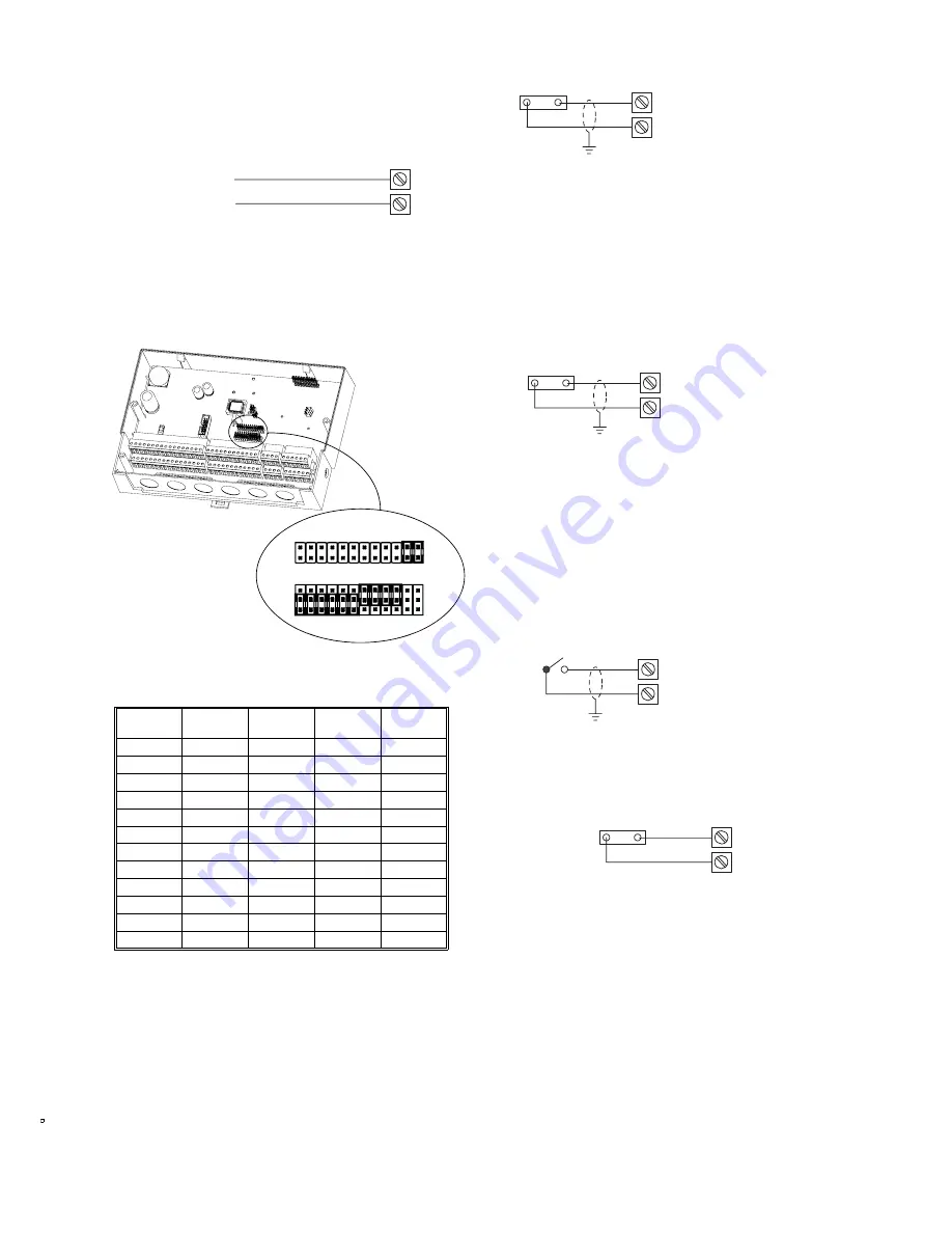
S-Link Sensor Wiring
1.
Review the Precautions section.
2.
Connect unscreened cable to terminals
39
and
78
. Polarity makes
no difference.
See the MN-Sx data sheet (DS 10.000A) for sensor connection
details.
Universal Input (UI) Wiring
UI Configuration
Each UI must be configured as either a Voltage (0 to 10Vdc),
Resistive/Temperature (0-10k
Ω
), or Digital Input. This must match the
usage of the UI in the controller application. Configuration is achieved
by placing the shorting block (jumper) onto the appropriate pins:
Refer to the controller’s 'Controller Definition Drawing' in VisiSat for a
picture of the required UI jumper settings for the controller. Factory
default configuration is shown in the following table. If an input is not
used, leave jumper in the default position.
Note: Each device connected to a UI must use a separate signal and
return conductor. If screened cable is used, connect the screen to
ground at one end only.
Voltage UIs
Note: An externally powered 0 to 10Vdc sensor is required. The input
impedance of a voltage input is 430k
Ω
.
1.
Review the Precautions section.
2.
Connect positive signal wire from 0 to 10Vdc device to desired
input terminal (18, 19, 20, 21, 22, 23, 24, 25, 26, 27, 28 or 29).
3.
Connect negative signal wire to one UI common (COM ) terminal
(57, 58, 59, 60, 61, 62, 63, 64, 65, 66, 67, 68).
4.
Make certain jumper is in Voltage position.
Resistive (Temperature) UIs
1.
Review the Precautions section.
2.
Connect one wire from the resistive device to desired input
terminal (18, 19, 20, 21, 22, 23, 24, 25, 26, 27, 28 or 29). Polarity
is not important.
3.
Connect other wire to UI common (COM ) terminal (57, 58, 59, 60,
61, 62, 63, 64, 65, 66, 67, 68).
4.
Make certain input configuration jumper is in Resistive position.
Digital UIs
Note: Only dry (voltage free) contacts can be monitored. Maximum
count frequency is once every two seconds.
1.
Review the Precautions section.
2.
Connect one wire from field contact to desired input terminal (18,
19, 20, 21, 22, 23, 24, 25, 26, 27, 28 or 29). Polarity is not
important.
3.
Connect other wire to one UI common (COM) terminal (57, 58, 59,
60, 61, 62, 63, 64, 65, 66, 67, 68).
4.
Make certain input configuration jumper is in Digital position.
Wiring for 15Vdc Source
The 15Vdc terminal can provide a 25mA source for use with a DUSF
sensor.Connect load to terminal 38 and 77.
Terminal
Number
Input
Number
Resistive
A
Digital
B
Voltage
C
18
1
Link 1A
19
2
Link 2A
20
3
Link 3A
21
4
Link 4A
22
5
Link 5A
23
6
Link 6A
24
7
Link 7B
25
8
Link 8B
26
9
Link 9B
27
10
Link 10B
28
11
Link 11C
29
12
Link 12C
{
S-Link Sensor
39
78
1 2 3 4 5 6 7
8 9 10 11 12 13 14 15 16 17
18 19 20 21 22 23 24 25 26 2
7 28 29
30 31 32 33
34 35 36 37 38 39
40 41 42 43 44 45 46 47
48 49 50 51 52 53 54 55
56
57 58 59 60 61 62 63 64 65 6
6 67 68
69 70 71 72
73 74 75 76 77 78
B = Digital
C = Voltage
A = Resistive
1 2 3 4 5 6 7 8 9 10 11 12
1 2 3 4 5 6 7 8 9 10 11 12
LK19
LK7
A
B
C
- +
Configure input as Voltage UI
18, 19, 20, 21, 22, 23, 24, 25, 26, 27, 28
or 29
57, 58, 59, 60, 61, 62, 63, 64, 65, 66, 67
or 68
Refer to the Wiring Routing Rules section.
18, 19, 20, 21, 22, 23, 24, 25, 26, 27, 28
or 29
57, 58, 59, 60, 61, 62, 63, 64, 65, 66, 67
or 68
Configure input as Resistive UI:
Refer to the Wiring Routing Rules section.
Configure input as Digital UI:
18, 19, 20, 21, 22, 23, 24, 25, 26, 27, 28
or 29
57, 58, 59, 60, 61, 62, 63, 64, 65, 66, 67
or 68
Refer to the Wiring Routing Rules section.
15Vdc load
38
77


