34
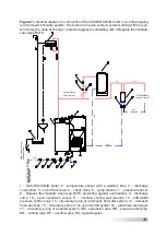
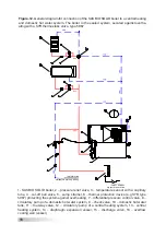
Figure.12.
General diagram for connection of the SAS BIO SOLID boiler to a central heating
and domestic hot water system. The boiler in the sealed system, secured against overhe-
ating with a SYR thermostatic valve, type 5067
1- SAS BIO SOLID boiler, 2 – pressure relief valve, 3 – temperature sensor with a capillary
tube, 4 – cut-off ball valve, 5 – sump strainer, 6 – thermal protection device (e.g SYR type
5067) protecting the system against overheating, 7 – differential pressure control valve, 8 –
circulatory pump of a domestic hot water system, 9 – check valve, 10 – domestic hot water
tank, 11 – four-way valve, 12 – circulatory pump of a central heating system, 13 – central
heating system, 14 – diaphragm expansion vessel, 15 – discharge valve, 16 – overflow
cooling well (vessel)
Supply from the installation
water system
water dump into the
sewage system


